Tag Archives: farm tractor

China FT800.38.211 Bolts For Foton Lovol Agricultural Genuine tractor Spare Parts Farm Tractors agricultural spare parts suppliers

Problem: New
Guarantee: 3 months
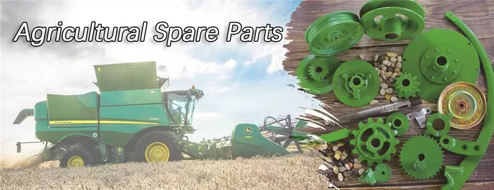
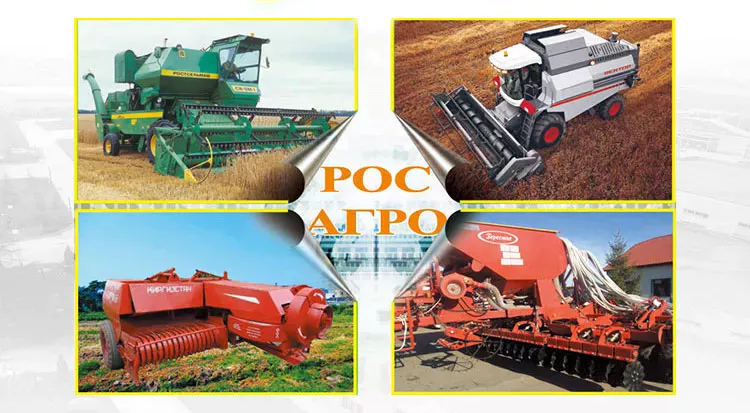
Relevant Industries: Machinery Repair Outlets, Farms
Bodyweight (KG): .1 KG
Showroom Spot: None
Video outgoing-inspection: Not Obtainable
Equipment Take a look at Report: Not Available
Advertising Sort: New Merchandise 2571
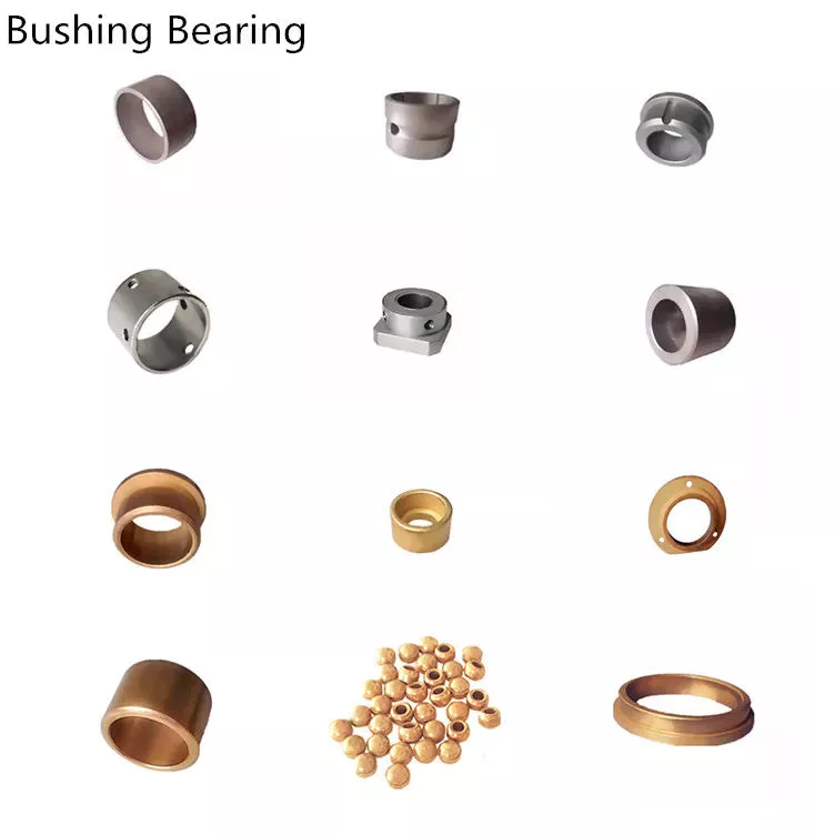
Kind: Shafts
Use: Tractors
Merchandise Title: Driving Wheel Fixing Bolt
Packaging Particulars: opp
Port: HangZhou

Specification

itemBolt
ConditionNew
Place of OriginChina,ZheJiang
Package dimension(CM)10*6*six
Gross fat(KG)0.five
Recommend Items Organization Profile Certifications Packing & Delivery FAQ 1. who are we?We are based in ZheJiang , China, start off from 2018,promote to Africa(40.00%),South Asia(twenty.00%),Eastern Asia(twenty.00%),Jap Europe(10.00%),North The us(ten.00%). There are overall about 5-10 men and women in our workplace.2. how can we guarantee quality?Always a pre-manufacturing sample prior to mass productionAlways ultimate Inspection ahead of shipment 2019 new design jetski boat trailer cuddy boat trailer cabin boat trailer 3.what can you purchase from us?Lovol tractor parts,Quanchai elements,Foton tractor portion,Weichai elements,tractor engine parts4. why ought to you purchase from us not from other suppliers?Our firm is engaged in CZPT tractor parts, with more than 10 years of provider encounter at home and abroad, with good expert understanding and ample inventory.5. what services can we provide?Approved Delivery Terms: FOB,CFR,CIF,EXW,Specific Delivery;Accepted Payment Currency:USD, YF01 Line CuttingOil InjectionWinding Custom made Numerous Massager Electrical Metal Motor Parts Stator And Rotor Laminated Cores EUR,HKD,CNYAccepted Payment Sort: T/T,L/C,D/P D/A,MoneyGram,Credit history Card,PayPal,Western Union,Income,Escrow Large top quality NUP 306 Cylindrical roller bearing NU NN NUP NJ 306 305 Language Spoken:English,Chinese

agriculturalparts

Preventative Maintenance on Tractor Parts

You should not take your tractor out of commission by replacing the parts that are not working properly. You should be proactive about maintaining your tractor parts to ensure that they work well and are of the highest quality. You should also check if the company is 10 years old or more, as this will ensure that they have enough experience to handle warranty issues and any other problems. Lastly, you should check if the tractor parts company has a good reputation. Having a long standing company that is available around the clock is a plus.

Preventative maintenance of tractor parts

Performing preventative maintenance on tractor parts will help you avoid unexpected breakdowns and enhance its efficiency. Whether you’re the sole owner of a tractor or a part-owner, you should know which parts you need and where to find them. Having spares available is also important, as they can help you solve problems quickly. Listed below are some of the parts you need to know about. These components are essential for your tractor’s engine.

To maintain your tractor’s internal components, check for wear. Lubricate internal parts regularly to reduce friction. When possible, bring your tractor to a dealer for a thorough inspection. Additionally, remember to keep the tractor’s air filter clean. Dust in the air strains the tractor’s engine, and a dirty air filter can cause a lot of damage. By following the manufacturer’s instructions for proper maintenance, you can avoid costly repairs down the road.

For oil changes, check the owner’s manual for recommended oil change intervals. Make notes in the manual about the parts you’ll need. You can also refer to the manufacturer’s PM checklist. Depending on the type of tractor you own, you may need to change the oil once a year or more often. To keep your tractor running optimally, drain old oil after every use. The same goes for hydraulic fluid. Over time, it can become contaminated with particles and water. Therefore, it’s best to change it every year.

Modern tractors use a cooling system with fans and radiators. This system operates in varying temperatures and if it breaks down, you risk damaging the engine’s core parts. In addition, you should store your tractor’s battery under climate control. A battery maintainer can be purchased at any auto parts store. It’s a great idea to regularly inspect your tractor’s engine for problems as early as possible.

Types of tractor clutches

In a modern tractor, there are many types of transmission systems, and this article compares the pros and cons of each type. The original drive system of tractors relied on a clutch to change gears and range and engage/disengage the PTO drive. The clutch was usually a two-stage design; a full depression disengaged all drive systems while a partial depression only disengaged the gearbox. Today, these systems are independent.

The friction plate is a steel plate with a splined central hub. It features annular friction facings and is held between the flywheel and pressure plate. It has splines that limit its axial travel along the gearbox’s driving shaft and dampen torsional vibrations. Single-plate clutches are most commonly used in heavy agricultural equipment. While they were initially developed as a cost-effective alternative to drum brakes, they quickly gained popularity due to their low price and ease of use.

Another type of tractor clutch is the wrap-spring. These use a special cast-iron spring. This spring is able to transmit torque to the driven plate when the tractor is operating at normal engine speed, while the clutch springs help transmit torque to the driven plate when the engine is running at high engine speeds. The wrap-spring clutches must be lubricated with light oil and should be checked for deterioration after a few years.

The advantages and disadvantages of these types of clutches are explained briefly. They are generally made from high-quality materials and contain a high copper content. They have high-friction properties and can transfer heat effectively to the engine. The friction coefficient of these types of clutches ranges from 0.33 to 0.4. As a result, they are the best choice for intensive applications. In conclusion, there are many advantages and disadvantages of each type of tractor clutch.

agriculturalparts

Types of tractor transmission gears

There are several different types of tractor transmission gear. One of the most common is hydrostatic. A hydrostatic transmission works like a standard manual transmission, and operates with a pedal. To operate a hydrostatic transmission, you simply select the gear and engine speed you want, push the pedal, and the hydraulic oil turns the gears. Because this type of transmission is clutchless, it provides smooth forward/backward operation without the need for a manual shifter.

Tractor transmissions come in several types and have different features. Some of these systems are better for certain types of work than others, and you’ll find different types depending on the size and type of your tractor. Many tractors have two types of transmissions: geared speed and power shift. Each type offers different benefits, and they vary in cost and ease of use. There’s a geared speed transmission, a synchromesh transmission, and a power shift transmission.

A CVT (continuously variable transmission) is another popular option. Like hydro, CVTs use a belt to transfer power from the engine to the wheels. These tractors can shift gears with little effort. These tractors can reach up to four speeds without the need for a clutch. Powershift transmissions are simpler and more durable than CVTs. They’re also easier to repair. But a CVT may be the better choice for your farm tractor.

Hydrostatic and power shuttle transmissions allow you to shift gears and direction without the use of a clutch. Hydrostatic transmissions are usually hydraulically actuated, which makes it easy to change gears without using the clutch. Similarly, power shuttle transmissions are great for heavy-duty forward-and-reverse shifting. In either case, the clutches are hydraulically actuated and bathed in oil.

Types of CZPT fittings

In a nutshell, there are two types of CZPT fittings: standard and grease-fill. Standard CZPTs have three to four pumps of grease per fitting. Grease-filled CZPTs tend to attract dirt, dust, and sand, which can damage moving parts. Keeping these parts clean is crucial to their long-term performance. Using a rag to wipe off excess grease is an excellent way to ensure that the seals remain as sealed as possible.

There are different types of grease-filling tools available. Some are specifically designed to clear blocked CZPTs. These tools are used to fill the CZPT fitting with grease or diesel fuel and hit the fitting with a hammer. Be sure to use high-quality fitting rejuvenators, as cheap ones are less effective. These are also harder to find than grease-filling tools. To avoid these issues, use the proper tools when servicing your tractor.

CZPT fittings are used for many different kinds of tractor parts. You may find them on lawn equipment, construction equipment, and farming equipment. If you are unsure of what type your equipment has, ask your local CZPT dealer or visit one of their 17,000 CZPT AutoCare locations. Don’t forget to regularly grease these parts for the best performance. When you don’t have time to do so, they can lead to costly repairs.

Standard CZPTs feature a dome-shaped nipple that makes it easy to spot. Flow-stop fittings feature a ball check valve that reduces backflow during lubrication. Drive-type CZPTs feature a special coupler with a cross-pin to provide a positive lock. This type of grease CZPT eliminates the need for tapping during servicing.

agriculturalparts

Preventative maintenance of tractor’s CZPT fittings

Proper grease application and regular inspections are important parts of CZPT fittings. If a CZPT becomes stuck in an opening, the ball may not be able to come out. Lubrication around CZPTs is important as grease can damage the components and cause bigger problems. A tractor’s CZPT fittings are part of the tractor’s electrical system, so it is important to replace them when they become damaged.

Grease CZPTs allow the addition of grease at the manufacturer’s specifications. These fittings consist of a spring and metal ball inside a nipple. The grease gun compresses the spring and releases the ball from the nipple opening. Grease CZPTs are essential parts of heavy equipment, as a failed grease CZPT may cause brake failures and other systems to fail. Failure to maintain these fittings can cause rollover accidents.

Greasing the CZPTs is a vital part of regular tractor maintenance. Greasing the CZPTs will prevent your tractor’s bearings from sticking and make your work easier. Grease the CZPTs on pivot points and joints to keep them lubricated and running smoothly. For easy grease application, consider using a battery-powered grease gun. Once you have lubricated the CZPTs, you can move on to other parts of the tractor.

In addition to grease, you should check for leaks on your tractor’s CZPTs regularly. If you notice dirt buildup, there might be a leak. You can also check for any worn hoses to avoid major problems. If there is a leak, tighten the fittings and replace worn ones as soon as possible to avoid further damage. By performing these tasks regularly, you can increase the efficiency of your tractor and avoid unexpected breakdowns.

China FT800.38.211 Bolts For Foton Lovol Agricultural Genuine tractor Spare Parts Farm Tractors     agricultural spare parts suppliersChina FT800.38.211 Bolts For Foton Lovol Agricultural Genuine tractor Spare Parts Farm Tractors     agricultural spare parts suppliers
editor by czh 2023-07-03

China factory Quality Small Gasoline Diesel Farm Garden Power Tiller Cultivator Rotary Tillage Machine Walking Tractor Disc Harrow Parts Outer Tyre near me manufacturer

Product Description

Quality Small Gasoline Diesel Farm Garden Power Tiller Cultivator Rotary Tillage Machine Walking Tractor Disc Harrow Parts Outer Tyre

Notes: What you see is ONLY a Small Part of our products Scope, you are pleased to let us know your exact parts requirement so that we can offer you the Right Parts with Right Cost, Just Right with US!


We Also Supply Other models of Tiller Parts , Feel Free to contact us for more information. Can Also Check CZPT Online to get our latest updates.

When your axle needs to be replaced

If you’re wondering when your axle needs to be replaced, you should be aware of these signs first. A damaged axle is usually a sign that your car is out of balance. To tell if the axle needs to be replaced, listen for the strange noise the wheels make as they move. A rhythmic popping sound when you hit bumps or turns indicates that your axle needs to be replaced. If this sounds familiar, you should visit a mechanic.
Driveshaft

Symptoms of a broken shaft

You may notice a clicking or clanking sound from the rear of the vehicle. The vibrations you feel while driving may also indicate damaged axles. In severe cases, your car may lose control, resulting in a crash. If you experience these symptoms, it’s time to visit your auto repair shop. For just a few hundred dollars, you can get your car back on the road, and you don’t have to worry about driving.
Often, damaged axles can be caused by a variety of causes, including poor shock or load bearing bearings. Other causes of axle problems can be an overloaded vehicle, potholes, or a car accident. A bad axle can also cause vibrations and power transmission failures while driving. A damaged axle can also be the result of hitting a curb or pothole. When shaft damage is the cause of these symptoms, it must be repaired immediately.
If your car’s front axle is bent, you may need to replace them at the same time. In this case, you need to remove all tires from the car, separate the driveshaft from the transmission, and remove the axle. Be sure to double check the alignment to make sure everything is ok. Your insurance may cover the cost of repairs, but you may need to pay a deductible before getting coverage.
Axle damage is a common cause of vehicle instability. Axles are key components of a car that transmit power from the engine to the wheels. If it breaks, your vehicle will not be able to drive without a working axle. Symptoms of damaged axles can include high-speed vibrations or crashes that can shake the entire car. When it breaks down, your vehicle won’t be able to carry the weight of your vehicle, so it’s important to get your car repaired as soon as possible.
When your axle is damaged, the wheels will not turn properly, causing the vehicle to crash. When your car has these problems, the brakes won’t work properly and can make your car unstable. The wheels also won’t line up properly, which can cause the brakes to fail. Also, a damaged axle can cause the brakes to become sluggish and sensitive. In addition to the obvious signs, you can also experience the sound of metal rubbing against metal.

Types of car axles

When you’re shopping for a new or used car, it’s important to know that there are different types of axles. Knowing the year, make, model, trim and body type will help you determine the type you need. For easy purchasing, you can also visit My Auto Shop and fill out the vehicle information checklist. You can also read about drivetrains and braking systems. After mastering the basic information of the vehicle, you can purchase the axle assembly.
There are 2 basic types of automotive axles: short axles and drive axles. The axle is the suspension system of the vehicle. They carry the drive torque of the engine and distribute the weight throughout the vehicle. While short shafts have the advantage of simpler maintenance, dead shafts are more difficult to repair. They’re also less flexible, which means they need to be durable enough to withstand harsh conditions.
Axles can be 1 of 3 basic types, depending on the weight and required force. Semi-floating shafts have a bearing in the sleeve. They attach to the wheel and spin to generate torque. Semi-pontoons are common in light pickup trucks and medium-duty vehicles. They are not as effective as floating axles, but still provide a solid foundation for wheel alignment. To keep the wheels aligned, these axles are an important part of the car.
The front axle is the largest of the 3 and can handle road shocks. It consists of 4 main parts: stub shaft, beam, universal pin and track rod. The front axle is also very important as it helps with steering and handling road shocks. The front axle should be strong and durable, as the front axle is most susceptible to road shocks.
Cars use 2 types of axles: live and dead. Live axles connect to the wheels and drive the vehicle. Dead axles do not drive the wheels and support the vehicle. Those with 2 wheels have live axles. Heavy trucks and trailers use 3 or more. The number of axles varies according to the weight and load of the vehicle. This will affect which type of axle you need.
Driveshaft

life expectancy

There are a few things to keep in mind when determining the life expectancy of an automotive axle. First, you should check for any signs of wear. A common sign is rust. If your vehicle is often driven in snow and ice, you may need to replace the axle. Also, you should listen for strange sounds from the wheels, such as rhythmic thumping.
Depending on the type of axle, your car may have an average lifespan of 70,000 miles. However, if you have an older car, the CV axles probably won’t last 5 years. In this case, you may wish to postpone the inspection. This way, you can save money on repairs. However, the next step is to replace the faulty CV shaft. This process can take anywhere from 1 hour to 3 hours.
Weaker axles will eventually break. If it were weakened, it would compromise the steering suspension, putting other road users at risk. Fortunately, proper maintenance will help extend the life of your axle. Here are some tips for extending its lifespan. A good rule of thumb is to never go over speed bumps. This will cause sudden breakage, possibly resulting in a car accident. To prolong the life of your vehicle’s axles, follow these tips.
Another thing to check is the CV connector. If loose, it can cause vibration or even breakage if not controlled. Loose axles can damage the body, suspension and differential. To make matters worse, the guard on the CV joint could tear prematurely, causing the shaft to come loose. Poor CV connections can damage the differential or transmission if left unchecked. So if you want to maximize the life expectancy of your car’s axles, consider getting them serviced as soon as possible.
Driveshaft

The cost of repairing a damaged axle

A damaged axle may need repair as it is responsible for transferring power from the engine to the wheels. A damaged axle can cause a crash or even loss of control. Repairing an axle is much simpler than dealing with an accident. However, damaged axles can cost hundreds of dollars or more. Therefore, it is important to know what to do if you suspect that your axle may have a damaged component.
When your car needs to be replaced or repaired, you should seek the help of a professional mechanic to keep your car safe. You can save a lot of money by contacting a local mechanic who will provide the parts and labor needed to repair the axle. Also, you can avoid accidents by fixing your car as soon as possible. While axles can be expensive, they can last for many years.
The cost of repairing a damaged axle depends on the amount of repairs required and the vehicle you are driving. Prices range from $300 to $1,000, depending on the car and its age. In most cases, it will cost you less than $200 if you know how to fix a damaged axle. For those without DIY auto repair experience, a new axle can cost as little as $500. A damaged axle is a dangerous part of driving.
Fortunately, there are several affordable ways to repair damaged axles. Choosing a mechanic who specializes in this type of repair is critical. They will assess the damage and decide whether to replace or repair the part. In addition to this, they will also road test your car after completing the repairs. If you are unsure about repair procedures or costs, call a mechanic.

China factory Quality Small Gasoline Diesel Farm Garden Power Tiller Cultivator Rotary Tillage Machine Walking Tractor Disc Harrow Parts Outer Tyre     near me manufacturer China factory Quality Small Gasoline Diesel Farm Garden Power Tiller Cultivator Rotary Tillage Machine Walking Tractor Disc Harrow Parts Outer Tyre     near me manufacturer

China manufacturer Best Quality 50HP 4X4 Agricultural Farm Tractor and Mini Tractor for Sale Tractor Modified Part near me supplier

Product Description

High quality 4wd tractor with competitive prices

We will provide :
1.English manual with sketches of machine structure of this standard model;
2.Full catalog of QILU tractor for reselling(pictures and videos for customers reselling);
3.Full videos about operating teaching including the after sale services steps;
4.Extra filters and toolbox for easy maitain;
5.Spare parts by air express(low weight);
6.30% advance payment for production starting,the balance after the customer’s confirmation by videos and pictures.

Product Parameters


Model

QL-504B

Model

QL-504B

Power(kw)

36.8

Driving mode

4X4 4WD

Lengt(mm)

33/8822 0571 .1

Front tread(mm)

1200

Reverse speed(km/h)

2.52-11.65

Rear tread(mm)

1100

PTO(r/min)

720/540

Our Advantages

1. The body is short and the turning radius is small, suitable for flexible steering in the orchard.
2. The low body design makes it easy for the tractor to travel in the orchard and grape racks.
3. The exhaust pipe is designed underneath to prevent high temperature and toxic gas from spraying upwards and harm the leaves and fruits of fruit trees.
4. Combined with the working environment of Italian vineyards, design and develop together with Italian tractor engineers.


Detailed Photos


Packing and Shipping

Other Products


Company Profile


  ZheJiang Qilu Industry is a manufacturing enterprise that develops, produces and sells high-end non-road machinery and equipment. The industrial park was established in 2016 with a total investment of 1 billion yuan, covering an area of more than 300 acres, and designing and producing 50,000 units (sets) of machinery and equipment products annually. The company’s main business includes agricultural equipment and construction machinery. The agricultural equipment business focuses on the R&D and manufacturing of high-end smart tractors. Construction machinery focuses on the development and manufacturing of excavators and loaders. The production and sales volume of more than 10,000 units ranks among the top 6 in the industry.
  
    Our goal is to create high-quality, highly competitive products that can quickly open and occupy the market. At the same time, we provide distributors with high-quality after-sales service and strong support, so that we can grow together and achieve a CZPT situation.
    Distributors from various countries are welcome to settle in.

FAQ

Are you a manufacturer or Trader ?

We are a professional manufacture , we have our own R&D team and sales team, we provide one-stop service.

What is your payment term ?
We accept T/T, L/C at sight, Western Union, Paypal etc.

How long is the validity of quotation ?
Generally,our price is valid within 1 month from the date of quotation .The price will be adjusted appropriately according to the price fluctuation of raw material and changes in market .

What is your delivery time ?
Usually, we make merchandise inventory, if we have the products in stock, the delivery time is 5-10 days after receiving the deposit.
If we don’t have the products in stock, we will arrange the production right now, the delivery time will be 30-45 days,It depend on the order quantity.

Do you provide OEM/ODM Service ?
Yes, offer me necessary information, we provide custom-make service to meet different needs of global clients with different budgets

Do you have CE certificate ?
Yes, most of our products have the CE certificate

How can we ensure quality?
The final inspection is always carried out before shipment.

How to install the equipment after purchasing ?
We will provide professional installation video to illustrate.Also provide manual.

Do you offer a guarantee?
Yes, we guarantee our product for 1 year. Provide after-sales service support andagricultural technical support.

What is your MOQ?
1Sets

Types of Bevel Gears

Bevel Gears are used in a number of industries. They are used in wheeled excavators, dredges, conveyor belts, mill actuators, and rail transmissions. A bevel gear’s spiral or angled bevel can make it suitable for confined spaces. It is also used in robotics and vertical supports of rolling mills. You can use bevel gears in food processing processes. For more information on bevel gears, read on.
gear

Spiral bevel gear

Spiral bevel gears are used to transmit power between 2 shafts in a 90-degree orientation. They have curved or oblique teeth and can be fabricated from various metals. Bestagear is 1 manufacturer specializing in medium to large spiral bevel gears. They are used in the mining, metallurgical, marine, and oil fields. Spiral bevel gears are usually made from steel, aluminum, or phenolic materials.
Spiral bevel gears have many advantages. Their mesh teeth create a less abrupt force transfer. They are incredibly durable and are designed to last a long time. They are also less expensive than other right-angle gears. They also tend to last longer, because they are manufactured in pairs. The spiral bevel gear also reduces noise and vibration from its counterparts. Therefore, if you are in need of a new gear set, spiral bevel gears are the right choice.
The contact between spiral bevel gear teeth occurs along the surface of the gear tooth. The contact follows the Hertz theory of elastic contact. This principle holds for small significant dimensions of the contact area and small relative radii of curvature of the surfaces. In this case, strains and friction are negligible. A spiral bevel gear is a common example of an inverted helical gear. This gear is commonly used in mining equipment.
Spiral bevel gears also have a backlash-absorbing feature. This feature helps secure the thickness of the oil film on the gear surface. The shaft axis, mounting distance, and angle errors all affect the tooth contact on a spiral bevel gear. Adjusting backlash helps to correct these problems. The tolerances shown above are common for bevel gears. In some cases, manufacturers make slight design changes late in the production process, which minimizes the risk to OEMs.

Straight bevel gear

Straight bevel gears are among the easiest types of gears to manufacture. The earliest method used to manufacture straight bevel gears was to use a planer equipped with an indexing head. However, improvements have been made in manufacturing methods after the introduction of the Revacycle system and the Coniflex. The latest technology allows for even more precise manufacturing. Both of these manufacturing methods are used by CZPT. Here are some examples of straight bevel gear manufacturing.
A straight bevel gear is manufactured using 2 kinds of bevel surfaces, namely, the Gleason method and the Klingelnberg method. Among the two, the Gleason method is the most common. Unlike other types of gear, the CZPT method is not a universal standard. The Gleason system has higher quality gears, since its adoption of tooth crowning is the most effective way to make gears that tolerate even small assembly errors. It also eliminates the stress concentration in the bevelled edges of the teeth.
The gear’s composition depends on the application. When durability is required, a gear is made of cast iron. The pinion is usually 3 times harder than the gear, which helps balance wear. Other materials, such as carbon steel, are cheaper, but are less resistant to corrosion. Inertia is another critical factor to consider, since heavier gears are more difficult to reverse and stop. Precision requirements may include the gear pitch and diameter, as well as the pressure angle.
Involute geometry of a straight bevel gear is often computed by varying the surface’s normal to the surface. Involute geometry is computed by incorporating the surface coordinates and the theoretical tooth thickness. Using the CMM, the spherical involute surface can be used to determine tooth contact patterns. This method is useful when a roll tester tooling is unavailable, because it can predict the teeth’ contact pattern.
gear

Hypoid bevel gear

Hypoid bevel gears are an efficient and versatile speed reduction solution. Their compact size, high efficiency, low noise and heat generation, and long life make them a popular choice in the power transmission and motion control industries. The following are some of the benefits of hypoid gearing and why you should use it. Listed below are some of the key misperceptions and false assumptions of this gear type. These assumptions may seem counterintuitive at first, but will help you understand what this gear is all about.
The basic concept of hypoid gears is that they use 2 non-intersecting shafts. The smaller gear shaft is offset from the larger gear shaft, allowing them to mesh without interference and support each other securely. The resulting torque transfer is improved when compared to conventional gear sets. A hypoid bevel gear is used to drive the rear axle of an automobile. It increases the flexibility of machine design and allows the axes to be freely adjusted.
In the first case, the mesh of the 2 bodies is obtained by fitting the hyperboloidal cutter to the desired gear. Its geometric properties, orientation, and position determine the desired gear. The latter is used if the desired gear is noise-free or is required to reduce vibrations. A hyperboloidal cutter, on the other hand, meshes with 2 toothed bodies. It is the most efficient option for modeling hypoid gears with noise concerns.
The main difference between hypoid and spiral bevel gears is that the hypoid bevel gear has a larger diameter than its counterparts. They are usually found in 1:1 and 2:1 applications, but some manufacturers also provide higher ratios. A hypoid gearbox can achieve speeds of 3 thousand rpm. This makes it the preferred choice in a variety of applications. So, if you’re looking for a gearbox with a high efficiency, this is the gear for you.

Addendum and dedendum angles

The addendum and dedendum angles of a bevel gear are used to describe the shape and depth of the teeth of the gear. Each tooth of the gear has a slightly tapered surface that changes in depth. These angles are defined by their addendum and dedendum distances. Addendum angle is the distance between the top land and the bottom surface of the teeth, while dedendum angle is the distance between the pitch surface and the bottom surface of the teeth.
The pitch angle is the angle formed by the apex point of the gear’s pitch cone with the pitch line of the gear shaft. The dedendum angle, on the other hand, is the depth of the tooth space below the pitch line. Both angles are used to measure the shape of a bevel gear. The addendum and dedendum angles are important for gear design.
The dedendum and addendum angles of a bevel gear are determined by the base contact ratio (Mc) of the 2 gears. The involute curve is not allowed to extend within the base diameter of the bevel gear. The base diameter is also a critical measurement for the design of a gear. It is possible to reduce the involute curve to match the involute curve, but it must be tangential to the involute curve.
The most common application of a bevel gear is the automotive differential. They are used in many types of vehicles, including cars, trucks, and even construction equipment. They are also used in the marine industry and aviation. Aside from these 2 common uses, there are many other uses for bevel gears. And they are still growing in popularity. But they’re a valuable part of automotive and industrial gearing systems.
gear

Applications of bevel gears

Bevel gears are used in a variety of applications. They are made of various materials depending on their weight, load, and application. For high-load applications, ferrous metals such as grey cast iron are used. These materials have excellent wear resistance and are inexpensive. For lower-weight applications, steel or non-metals such as plastics are used. Some bevel gear materials are considered noiseless. Here are some of their most common uses.
Straight bevel gears are the easiest to manufacture. The earliest method of manufacturing them was with a planer with an indexing head. Modern manufacturing methods introduced the Revacycle and Coniflex systems. For industrial gear manufacturing, the CZPT uses the Revacycle system. However, there are many types of bevel gears. This guide will help you choose the right material for your next project. These materials can withstand high rotational speeds and are very strong.
Bevel gears are most common in automotive and industrial machinery. They connect the driveshaft to the wheels. Some even have a 45-degree bevel. These gears can be placed on a bevel surface and be tested for their transmission capabilities. They are also used in testing applications to ensure proper motion transmission. They can reduce the speed of straight shafts. Bevel gears can be used in many industries, from marine to aviation.
The simplest type of bevel gear is the miter gear, which has a 1:1 ratio. It is used to change the axis of rotation. The shafts of angular miter bevel gears can intersect at any angle, from 45 degrees to 120 degrees. The teeth on the bevel gear can be straight, spiral, or Zerol. And as with the rack and pinion gears, there are different types of bevel gears.

China manufacturer Best Quality 50HP 4X4 Agricultural Farm Tractor and Mini Tractor for Sale Tractor Modified Part     near me supplier China manufacturer Best Quality 50HP 4X4 Agricultural Farm Tractor and Mini Tractor for Sale Tractor Modified Part     near me supplier

China Best Sales Plow Disc Blade, Tractor Farm Machine Parts wholesaler

Product Description

Quick Details

Type:; Blades Use:; Cultivators Place of Origin:; ZheJiang ,; China (Mainland);
Brand Name:; dadi Model Number:; many color:; many
thickness:; Customer requirements

Packaging & Delivery

Packaging Details:; Iron frame or as customers requested
Delivery Detail:; Based on purchasing quantity

 
Product Description
Types of disc:; Notched/Plain/Smooth/Flat
Material:; 65 Manganese Steel
Diameter:; 12″-32″
Thickness:; 3-12 mm
Hardness:; 38 to 45 HRC
Our company is a professional manufacturer of plough and harrow disc blades.; We have a production line for farming discs producing,; cleaning and painting.;
We can produce discs made of 65 Manganese Steel from in 12″-32″
Diameter and from 3 to 12mm in thickness.; Annually output is 300,; 000 PCS.; The products exported to UK,; USA,; France,; Australia and South Africa,; etc.; More than 60 countries and districts.;
We can supply all various of discs according to customers drawings and samples.;
 
 
Specifications


Diameter Overall dimension Thickness
mm inch mm mm
305 12 19 3
330 13 25 3
355 14 38 3
410 15 38~50 3
430 17 57 3; 4
460 18 38~60 3; 4
480 19 57 3; 4
510 20 44~63 3; 4; 5
535 21 63 3; 4; 5
560 22 60~85 4; 5; 6
585 23 75~90 4; 5; 6
610 24 75~95 4; 5; 6
660 26 86~115 5; 6; 7; 8
710 28 100~130 5; 6; 7; 8
760 30 120~135 6; 7; 8; 10; 12
810 32 120~140 8; 10; 12


What Is a Pulley?

The pulley is a wheel mounted on a shaft or axle. Its purpose is to support the movement of a cable that is taut. This cable transfers power to a shaft. However, there are certain safety precautions that you should follow when using a pulley. Read on to learn more! Listed below are common uses and their main parts. Listed below are some of the benefits of using a pulley.
pulley

Common uses of a pulley

A pulley is a common mechanical device used to increase the force needed to lift a heavy object. Most commonly, these devices are used in construction equipment. These machines use high-10sion ropes to transfer heavy objects from 1 floor to another. Other common uses of a pulley include buckets and flagpoles. These devices are extremely useful in a wide range of applications. To learn more about the common uses of pulleys, keep reading.
A pulley is a wheel with grooves for holding rope. Its purpose is to change the direction and point at which a pulling force acts. It is usually used in sets to reduce the amount of force needed to lift a load, but the work involved is similar. Pulleys are also used in rock climbing devices. For many applications, a pulley is a vital part of construction.
The most common use of a pulley involves hoisting and lowering a flag. Other examples include clotheslines, bird feeders, and escalators. Pulleys are also commonly used on oil derricks. Many other common applications include hoisting and lowering garage doors. Pulley systems are also used in engines and cranes. For more information, check out our interactive pulley diagram!
Pulleys can also be used to lower total work required for a task. In many cases, a pulley will consist of 2 parts: the pulley hub and the shaft pulley. The hub clamps the shaft pulley, while the pulley itself is connected to the motor or other device. If you’re looking for a pulley, it’s important to learn how it works.
The most common uses for a pulley involve lifting heavy objects, and the mechanism used to lift them is known as a pulley. A pulley is an industrial device that uses 2 wheels to reduce the force needed to lift a weight. The pulley reduces this force by half by allowing the user to pull on the rope 4 times as far. The pulley also allows for a smaller lifting distance.

Main parts of a pulley

A pulley consists of the main element of a system. This is typically a cable, rope, belt, or chain. There are 2 basic types of pulleys – a Driver Pulley and a Follower Pulley. Pulleys are available in small and large sizes. The periphery part of the pulley is called the Face, and the protruding middle part is called the Crown. A pulley’s face can be round, rectangular, or even “V” shaped.
The first pulley was created by the Greek mathematician Archimedes in the third century BCE. These simple machines are made of a rope, an axle, and a wheel. The pulley’s end is attached to a person, object, or motor. These machines can be used in various tasks to lift heavy objects. The pulley is a great mechanical advantage for any lifter.
The ideal mechanical advantage of a pulley is defined by the number of rope segments that pull an object. The higher the number of loops on the rope, the higher the mechanical advantage. The greater the mechanical advantage, the less force is required to move the object. Likewise, the greater the distance the rope traverses, the higher the mechanical advantage of a pulley. There are several different types of pulley, depending on their combination of rope, wheel, and rope.
The basic components of a pulley are the face and hub, and the rope is threaded into the center of the pulley. The pulley is usually made of a rope and can be used to lift heavy weights. It can also be used to apply great force in any direction. Step pulleys have multiple faces, which are fixed in sequence. They can also increase the speed of the driven pulley.
A pulley is a simple machine consisting of a wheel, rope, or chain. These parts are crucial for making moving and lifting easier. Because they change the direction and magnitude of force, they can be a useful tool. Some pulleys even change direction. You can learn more about the pulley by downloading this resource today. The resources are designed to support the new 9-1 GCSEs in Design & Technology and Engineering.
pulley

Mechanical advantage

Pulleys have been used to move heavy objects for centuries. When 2 rope sections are used, the weight of a 100kg mass can be moved with only 500 newtons of force. Adding an extra pulley increases the mechanical advantage. If the pulley has 2 wheels, the distance between the rope sections and the wheel grooves is only half the distance, but the mechanical advantage still applies. Adding another pulley increases the mechanical advantage, but can be risky.
Mechanical advantage is the ratio of force used versus force applied. The calculations are made under the assumption that the ropes and weights do not elongate or lose energy due to friction. If the weights are very light, the mechanical advantage is greater than that in the real world. To calculate the mechanical advantage, the weight of the load to be lifted must be the same as the weight of the person using the pulley.
A single moveable pulley has a mechanical advantage of two. The weight passes around the pulley, and 1 end of the rope is attached to a fixed point. The pulling force is then applied to the other end of the rope. The distance the weight travels doubles, or halved, depending on the direction of the pulley. Adding a second pulley reduces the distance and the effort required to lift it.
There are several ways to calculate the mechanical advantage of a pulley system. Some methods are specific to certain types of systems, while others work for all systems. The T-Method is a good choice in many applications, as it calculates the units of tension for each rope segment. Once you have determined the input force, you need to determine the maximum force that will be applied to each component. A compound pulley, for example, will require 4 units of tension for each rope segment.
In simple terms, the effort is the amount of force needed to lift the load. This force is measured in newtons (N). A mechanical advantage is often presented without units. If the student does not have this unit, you may need to convert the units to newtons, since 1 kilogram is equal to 10 newtons. If you can’t figure out the units of effort, you can use the KWL chart provided by the teacher.
pulley

Safety precautions

There are a few safety precautions you should take when using a pulley. First, always check the SWL (safe working load) before attaching anything to the pulley. This indicates the maximum weight and angle the pulley can safely handle. Second, make sure that your work area is free from people and debris. Third, wear a hard hat to protect your head from blows and falling objects.
Another important consideration is anchoring. Although the pulley reduces the weight of an object, it is not enough to eliminate the weight. This is especially true if you are hoisting a heavy object, such as a motorcycle or lawnmower. It is important to ensure that the anchoring point can support the entire weight of the load. It is also important to follow proper anchoring procedures when using a pulley to lift a motorcycle or lawnmower.
In addition to the safety latch, you should use a tag line to control the suspended load. Remember that a chain pulley block is necessary for vertical lifting. You should also wear personal protective equipment (PPE) while using a pulley to avoid injuries. If your workplace does not have an PPE policy, you should consider implementing a similar policy. These safety guidelines are a good start.
If you are using a pulley to lift heavy objects, make sure to wear gloves. Those who are not familiar with rope-pulling will have an easier time demonstrating how it works. If you are using a rope-pulley system in a classroom, be sure to follow lab safety guidelines. Wear cloth gloves, clear the area, and do not jerk the rope. In addition, never allow yourself to be pulled into the rope by an unfamiliar person.
Another important safety precaution when using a pulley is to ensure that the anchor point for your system is adequate to support the weight of the object being lifted. Check with the manufacturer of the pulley to find out what its weight limit is, as some types of pulleys are designed to lift much heavier weights than others. It is important to follow all manufacturer’s instructions when using a pulley.

China Best Sales Plow Disc Blade, Tractor Farm Machine Parts     wholesaler China Best Sales Plow Disc Blade, Tractor Farm Machine Parts     wholesaler

China factory Agricultural Machine Equipment Farm Tractor 45HP 4X4wd Mini Diesel Power Engine Technical Parts with Hot selling

Product Description

Agricultural Machine Equipment Farm Tractor 45hp 4x4wd Mini Diesel Power Engine Technical Parts

Product Overview

The shift synchronizer makes shifting lighter and convenient.
Equipped flat tire as standard,Paddy tire optional.
Adopt transmission 8+8 shuttle for easier operation, which caters to different needs.

FEATURES AT A GLANCE

Good sealing perforamnce of axles ensure working in water or deep mud field.
Use double steering cylinders on front axle for reducing turning radius.
Air brake is optional for road transport.
High quality bearings are used for long work prolonging work life.
Equipped ROPS&Canopy as standard,Cabin optional for comfort.


PRODUCT SPECIFICATIONS

Company Profile

WORLD A/M has been dedicated to becoming a worldwide first-class agriculture machinery manufacture in the past decade. By high-quality products and customer-oriented service support, the company’s products command a good market both at home and in 58
countries and regions overseas. So far, more than 350,000 WORLD machines have been sold and uesd globally.


Analytical Approaches to Estimating Contact Pressures in Spline Couplings

A spline coupling is a type of mechanical connection between 2 rotating shafts. It consists of 2 parts – a coupler and a coupling. Both parts have teeth which engage and transfer loads. However, spline couplings are typically over-dimensioned, which makes them susceptible to fatigue and static behavior. Wear phenomena can also cause the coupling to fail. For this reason, proper spline coupling design is essential for achieving optimum performance.
splineshaft

Modeling a spline coupling

Spline couplings are becoming increasingly popular in the aerospace industry, but they operate in a slightly misaligned state, causing both vibrations and damage to the contact surfaces. To solve this problem, this article offers analytical approaches for estimating the contact pressures in a spline coupling. Specifically, this article compares analytical approaches with pure numerical approaches to demonstrate the benefits of an analytical approach.
To model a spline coupling, first you create the knowledge base for the spline coupling. The knowledge base includes a large number of possible specification values, which are related to each other. If you modify 1 specification, it may lead to a warning for violating another. To make the design valid, you must create a spline coupling model that meets the specified specification values.
After you have modeled the geometry, you must enter the contact pressures of the 2 spline couplings. Then, you need to determine the position of the pitch circle of the spline. In Figure 2, the centre of the male coupling is superposed to that of the female spline. Then, you need to make sure that the alignment meshing distance of the 2 splines is the same.
Once you have the data you need to create a spline coupling model, you can begin by entering the specifications for the interface design. Once you have this data, you need to choose whether to optimize the internal spline or the external spline. You’ll also need to specify the tooth friction coefficient, which is used to determine the stresses in the spline coupling model 20. You should also enter the pilot clearance, which is the clearance between the tip 186 of a tooth 32 on 1 spline and the feature on the mating spline.
After you have entered the desired specifications for the external spline, you can enter the parameters for the internal spline. For example, you can enter the outer diameter limit 154 of the major snap 54 and the minor snap 56 of the internal spline. The values of these parameters are displayed in color-coded boxes on the Spline Inputs and Configuration GUI screen 80. Once the parameters are entered, you’ll be presented with a geometric representation of the spline coupling model 20.

Creating a spline coupling model 20

The spline coupling model 20 is created by a product model software program 10. The software validates the spline coupling model against a knowledge base of configuration-dependent specification constraints and relationships. This report is then input to the ANSYS stress analyzer program. It lists the spline coupling model 20’s geometric configurations and specification values for each feature. The spline coupling model 20 is automatically recreated every time the configuration or performance specifications of the spline coupling model 20 are modified.
The spline coupling model 20 can be configured using the product model software program 10. A user specifies the axial length of the spline stack, which may be zero, or a fixed length. The user also enters a radial mating face 148, if any, and selects a pilot clearance specification value of 14.5 degrees or 30 degrees.
A user can then use the mouse 110 to modify the spline coupling model 20. The spline coupling knowledge base contains a large number of possible specification values and the spline coupling design rule. If the user tries to change a spline coupling model, the model will show a warning about a violation of another specification. In some cases, the modification may invalidate the design.
In the spline coupling model 20, the user enters additional performance requirement specifications. The user chooses the locations where maximum torque is transferred for the internal and external splines 38 and 40. The maximum torque transfer location is determined by the attachment configuration of the hardware to the shafts. Once this is selected, the user can click “Next” to save the model. A preview of the spline coupling model 20 is displayed.
The model 20 is a representation of a spline coupling. The spline specifications are entered in the order and arrangement as specified on the spline coupling model 20 GUI screen. Once the spline coupling specifications are entered, the product model software program 10 will incorporate them into the spline coupling model 20. This is the last step in spline coupling model creation.
splineshaft

Analysing a spline coupling model 20

An analysis of a spline coupling model consists of inputting its configuration and performance specifications. These specifications may be generated from another computer program. The product model software program 10 then uses its internal knowledge base of configuration dependent specification relationships and constraints to create a valid three-dimensional parametric model 20. This model contains information describing the number and types of spline teeth 32, snaps 34, and shoulder 36.
When you are analysing a spline coupling, the software program 10 will include default values for various specifications. The spline coupling model 20 comprises an internal spline 38 and an external spline 40. Each of the splines includes its own set of parameters, such as its depth, width, length, and radii. The external spline 40 will also contain its own set of parameters, such as its orientation.
Upon selecting these parameters, the software program will perform various analyses on the spline coupling model 20. The software program 10 calculates the nominal and maximal tooth bearing stresses and fatigue life of a spline coupling. It will also determine the difference in torsional windup between an internal and an external spline. The output file from the analysis will be a report file containing model configuration and specification data. The output file may also be used by other computer programs for further analysis.
Once these parameters are set, the user enters the design criteria for the spline coupling model 20. In this step, the user specifies the locations of maximum torque transfer for both the external and internal spline 38. The maximum torque transfer location depends on the configuration of the hardware attached to the shafts. The user may enter up to 4 different performance requirement specifications for each spline.
The results of the analysis show that there are 2 phases of spline coupling. The first phase shows a large increase in stress and vibration. The second phase shows a decline in both stress and vibration levels. The third stage shows a constant meshing force between 300N and 320N. This behavior continues for a longer period of time, until the final stage engages with the surface.
splineshaft

Misalignment of a spline coupling

A study aimed to investigate the position of the resultant contact force in a spline coupling engaging teeth under a steady torque and rotating misalignment. The study used numerical methods based on Finite Element Method (FEM) models. It produced numerical results for nominal conditions and parallel offset misalignment. The study considered 2 levels of misalignment – 0.02 mm and 0.08 mm – with different loading levels.
The results showed that the misalignment between the splines and rotors causes a change in the meshing force of the spline-rotor coupling system. Its dynamics is governed by the meshing force of splines. The meshing force of a misaligned spline coupling is related to the rotor-spline coupling system parameters, the transmitting torque, and the dynamic vibration displacement.
Despite the lack of precise measurements, the misalignment of splines is a common problem. This problem is compounded by the fact that splines usually feature backlash. This backlash is the result of the misaligned spline. The authors analyzed several splines, varying pitch diameters, and length/diameter ratios.
A spline coupling is a two-dimensional mechanical system, which has positive backlash. The spline coupling is comprised of a hub and shaft, and has tip-to-root clearances that are larger than the backlash. A form-clearance is sufficient to prevent tip-to-root fillet contact. The torque on the splines is transmitted via friction.
When a spline coupling is misaligned, a torque-biased thrust force is generated. In such a situation, the force can exceed the torque, causing the component to lose its alignment. The two-way transmission of torque and thrust is modeled analytically in the present study. The analytical approach provides solutions that can be integrated into the design process. So, the next time you are faced with a misaligned spline coupling problem, make sure to use an analytical approach!
In this study, the spline coupling is analyzed under nominal conditions without a parallel offset misalignment. The stiffness values obtained are the percentage difference between the nominal pitch diameter and load application diameter. Moreover, the maximum percentage difference in the measured pitch diameter is 1.60% under a torque of 5000 N*m. The other parameter, the pitch angle, is taken into consideration in the calculation.

China factory Agricultural Machine Equipment Farm Tractor 45HP 4X4wd Mini Diesel Power Engine Technical Parts     with Hot sellingChina factory Agricultural Machine Equipment Farm Tractor 45HP 4X4wd Mini Diesel Power Engine Technical Parts     with Hot selling

China Standard Good Service China Agricultural Equipment Factory Manufacturer to Supply Lifelong Tractor Parts for 25-280HP Farm CZPT with high quality

Product Description

Good service China agricultural equipment factory manufacturer to supply lifelong tractor parts for 25-280HP Farm Tractors

Tractor Main Features and Advantages:

1.Equipped famous brand engine showing advanced capacity,low fuel consumption,high economic efficiency.
2. Streamlined appearance design, beautiful and generous.
3.Transmission Case adopt meshed shift and add the gearbox interlock device makes the operation more smoothly,reliable and easier.
4. Double action clutch with disc spring, perform steadily and easy to operate.
5. Fully hydraulic steering system greatly reduced driver’s work strength.
6. Wet disc brake device, reliable brake performance.
7. Separate injection of hydraulic oil, reliable to operate.
8. The lifter with force and position adjustment, with reliable lift.
9. Tractor PTO:
PTO in Double speed : 540/760r/min Optional, For high working efficiency.
PTO shaft of 6 or 8 spline Optional, adaptable for agricultural equipment of all over the world. 
10. Big Chassis and Heavy-duty Rear axle for Durable Strong machine.
11. Full series light, ROPS,Sunshade/Canopy, Fan/Heater/Air-conditioned cabin are all available, for more comfortable driving environment. 

Tractor detail show :

Advance Production workshop :

Strictly inspect for every set machine before Goods Delivery :
Various Packing and Transporting ways to meet customers special request :

Perfect after-sale service for both Distributors and Private customers:

Please contact us if you have any demand for our product :

John li
Sales Director

HangZhou Yourchance Machinery Co., Ltd.
ADD: No.5097 CZPT East Street,HangZhou,China.
TEL:   

Best price will be quoted for you as soon as receive your Requirement !

The Four Basic Components of a Screw Shaft

There are 4 basic components of a screw shaft: the Head, the Thread angle, and the Threaded shank. These components determine the length, shape, and quality of a screw. Understanding how these components work together can make purchasing screws easier. This article will cover these important factors and more. Once you know these, you can select the right type of screw for your project. If you need help choosing the correct type of screw, contact a qualified screw dealer.

Thread angle

The angle of a thread on a screw shaft is the difference between the 2 sides of the thread. Threads that are unified have a 60 degree angle. Screws have 2 parts: a major diameter, also known as the screw’s outside diameter, and a minor diameter, or the screw’s root diameter. A screw or nut has a major diameter and a minor diameter. Each has its own angle, but they all have 1 thing in common – the angle of thread is measured perpendicularly to the screw’s axis.
The pitch of a screw depends on the helix angle of the thread. In a single-start screw, the lead is equal to the pitch, and the thread angle of a multiple-start screw is based on the number of starts. Alternatively, you can use a square-threaded screw. Its square thread minimizes the contact surface between the nut and the screw, which improves efficiency and performance. A square thread requires fewer motors to transfer the same load, making it a good choice for heavy-duty applications.
A screw thread has 4 components. First, there is the pitch. This is the distance between the top and bottom surface of a nut. This is the distance the thread travels in a full revolution of the screw. Next, there is the pitch surface, which is the imaginary cylinder formed by the average of the crest and root height of each tooth. Next, there is the pitch angle, which is the angle between the pitch surface and the gear axis.
screwshaft

Head

There are 3 types of head for screws: flat, round, and hexagonal. They are used in industrial applications and have a flat outer face and a conical interior. Some varieties have a tamper-resistant pin in the head. These are usually used in the fabrication of bicycle parts. Some are lightweight, and can be easily carried from 1 place to another. This article will explain what each type of head is used for, and how to choose the right 1 for your screw.
The major diameter is the largest diameter of the thread. This is the distance between the crest and the root of the thread. The minor diameter is the smaller diameter and is the distance between the major and minor diameters. The minor diameter is half the major diameter. The major diameter is the upper surface of the thread. The minor diameter corresponds to the lower extreme of the thread. The thread angle is proportional to the distance between the major and minor diameters.
Lead screws are a more affordable option. They are easier to manufacture and less expensive than ball screws. They are also more efficient in vertical applications and low-speed operations. Some types of lead screws are also self-locking, and have a high coefficient of friction. Lead screws also have fewer parts. These types of screw shafts are available in various sizes and shapes. If you’re wondering which type of head of screw shaft to buy, this article is for you.

Threaded shank

Wood screws are made up of 2 parts: the head and the shank. The shank is not threaded all the way up. It is only partially threaded and contains the drive. This makes them less likely to overheat. Heads on wood screws include Oval, Round, Hex, Modified Truss, and Flat. Some of these are considered the “top” of the screw.
Screws come in many sizes and thread pitches. An M8 screw has a 1.25-mm thread pitch. The pitch indicates the distance between 2 identical threads. A pitch of 1 is greater than the other. The other is smaller and coarse. In most cases, the pitch of a screw is indicated by the letter M followed by the diameter in millimetres. Unless otherwise stated, the pitch of a screw is greater than its diameter.
Generally, the shank diameter is smaller than the head diameter. A nut with a drilled shank is commonly used. Moreover, a cotter pin nut is similar to a castle nut. Internal threads are usually created using a special tap for very hard metals. This tap must be followed by a regular tap. Slotted machine screws are usually sold packaged with nuts. Lastly, studs are often used in automotive and machine applications.
In general, screws with a metric thread are more difficult to install and remove. Fortunately, there are many different types of screw threads, which make replacing screws a breeze. In addition to these different sizes, many of these screws have safety wire holes to keep them from falling. These are just some of the differences between threaded screw and non-threaded. There are many different types of screw threads, and choosing the right 1 will depend on your needs and your budget.
screwshaft

Point

There are 3 types of screw heads with points: cone, oval, and half-dog. Each point is designed for a particular application, which determines its shape and tip. For screw applications, cone, oval, and half-dog points are common. Full dog points are not common, and they are available in a limited number of sizes and lengths. According to ASTM standards, point penetration contributes as much as 15% of the total holding power of the screw, but a cone-shaped point may be more preferred in some circumstances.
There are several types of set screws, each with its own advantage. Flat-head screws reduce indentation and frequent adjustment. Dog-point screws help maintain a secure grip by securing the collar to the screw shaft. Cup-point set screws, on the other hand, provide a slip-resistant connection. The diameter of a cup-point screw is usually half of its shaft diameter. If the screw is too small, it may slack and cause the screw collar to slip.
The UNF series has a larger area for tensile stress than coarse threads and is less prone to stripping. It’s used for external threads, limited engagement, and thinner walls. When using a UNF, always use a standard tap before a specialized tap. For example, a screw with a UNF point is the same size as a type C screw but with a shorter length.

Spacer

A spacer is an insulating material that sits between 2 parts and centers the shaft of a screw or other fastener. Spacers come in different sizes and shapes. Some of them are made of Teflon, which is thin and has a low coefficient of friction. Other materials used for spacers include steel, which is durable and works well in many applications. Plastic spacers are available in various thicknesses, ranging from 4.6 to 8 mm. They’re suitable for mounting gears and other items that require less contact surface.
These devices are used for precision fastening applications and are essential fastener accessories. They create clearance gaps between the 2 joined surfaces or components and enable the screw or bolt to be torqued correctly. Here’s a quick guide to help you choose the right spacer for the job. There are many different spacers available, and you should never be without one. All you need is a little research and common sense. And once you’re satisfied with your purchase, you can make a more informed decision.
A spacer is a component that allows the components to be spaced appropriately along a screw shaft. This tool is used to keep space between 2 objects, such as the spinning wheel and an adjacent metal structure. It also helps ensure that a competition game piece doesn’t rub against an adjacent metal structure. In addition to its common use, spacers can be used in many different situations. The next time you need a spacer, remember to check that the hole in your screw is threaded.
screwshaft

Nut

A nut is a simple device used to secure a screw shaft. The nut is fixed on each end of the screw shaft and rotates along its length. The nut is rotated by a motor, usually a stepper motor, which uses beam coupling to accommodate misalignments in the high-speed movement of the screw. Nuts are used to secure screw shafts to machined parts, and also to mount bearings on adapter sleeves and withdrawal sleeves.
There are several types of nut for screw shafts. Some have radial anti-backlash properties, which prevent unwanted radial clearances. In addition, they are designed to compensate for thread wear. Several nut styles are available, including anti-backlash radial nuts, which have a spring that pushes down on the nut’s flexible fingers. Axial anti-backlash nuts also provide thread-locking properties.
To install a ball nut, you must first align the tangs of the ball and nut. Then, you must place the adjusting nut on the shaft and tighten it against the spacer and spring washer. Then, you need to lubricate the threads, the ball grooves, and the spring washers. Once you’ve installed the nut, you can now install the ball screw assembly.
A nut for screw shaft can be made with either a ball or a socket. These types differ from hex nuts in that they don’t need end support bearings, and are rigidly mounted at the ends. These screws can also have internal cooling mechanisms to improve rigidity. In this way, they are easier to tension than rotating screws. You can also buy hollow stationary screws for rotator nut assemblies. This type is great for applications requiring high heat and wide temperature changes, but you should be sure to follow the manufacturer’s instructions.

China Standard Good Service China Agricultural Equipment Factory Manufacturer to Supply Lifelong Tractor Parts for 25-280HP Farm CZPT     with high qualityChina Standard Good Service China Agricultural Equipment Factory Manufacturer to Supply Lifelong Tractor Parts for 25-280HP Farm CZPT     with high quality

China Professional Quality Small Gasoline Diesel Farm Garden Power Tiller Cultivator Rotary Tillage Machine Walking Tractor Disc Harrow Spare Parts Fender Mudguard near me factory

Product Description

Quality Small Gasoline Diesel Farm Garden Power Tiller Cultivator Rotary Tillage Machine Walking Tractor Disc Harrow Spare Parts Fender Mudguard

Notes: What you see is ONLY a Small Part of our products Scope, you are pleased to let us know your exact parts requirement so that we can offer you the Right Parts with Right Cost, Just Right with US!

We Also Supply Other models of Tiller Parts , Feel Free to contact us for more information. Can Also Check CZPT Online to get our latest updates.

Mechanical advantages of pulleys

A pulley is a mechanical device used to transmit motion. The device has a variety of uses, including lifting heavy objects. In this article, we will discuss the mechanical advantages, types, common uses and safety considerations of pulleys. We’ll also discuss how to identify pulleys and their components, and what to look out for when using pulleys. Read on to learn more about pulleys.
pulley

Mechanical advantages of pulleys

The mechanical advantage of pulleys is that they change the direction of force from 1 direction to another. In this way, the person lifting the heavy object can change its position with minimal effort. The pulleys are also easy to install and require no lubrication after installation. They are also relatively cheap. Combinations of pulleys and cables can be used to change the direction of the load.
The mechanical advantage of a pulley system increases with the number of ropes used in the system. The more cycles a system has, the more efficient it is. If the system had only 1 rope, the force required to pull the weight would be equal. By adding a second rope, the effort required to pull the weight is reduced. This increase in efficiency is known as the mechanical advantage of the pulley.
Pulleys have many uses. For example, ziplines are 1 application. This is a good example of pulleys in use today. Pulley systems can be complex and require a lot of space. Using ziplines as an example, advanced students can calculate the mechanical advantage of multiple pulleys by dividing the work done by each pulley by the remainder or fraction. Regents at the University of Colorado created a zipline with K-12 input.
Another use for pulleys is weight lifting. This technique is very effective when using multiple strands of rope. A single rope going from 1 pulley to the other with just 2 hands is not enough to lift heavy objects. Using a pulley system will greatly increase the force you receive. This power is multiplied over a larger area. So your lifting force will be much greater than the force exerted by a single rope.
The pulley is a great invention with many uses. For example, when lifting heavy objects, pulleys are a great way to get the job done, and it’s easier to do than 1 person. The pulley is fixed on a hinge and rotates on a shaft or shaft. Then pull the rope down to lift the object. A pulley assembly will make the task easier. In addition, it will also allow power to be transferred from 1 rotary shaft to another.
pulley

Types of pulleys

If you are an engineer, you must have come across different types of pulleys. Some pulleys come in multiple types, but a typical pulley has only 1 type. These types of pulleys are used in various industrial processes. Here are some common types of pulleys that engineers encounter on the job. In addition to the above, there are many more. If you haven’t seen them in practice, you can check out a list of the different types below.
Fixed pulleys: Fixed pulleys have a roller attached to a fixed point. The force required to pull the load through the fixed pulley is the same as the force required to lift the object. Movable pulleys allow you to change the direction of the force, for example, by moving it laterally. Likewise, movable pulleys can be used to move heavy objects up and down. Commonly used in multi-purpose elevators, cranes and weight lifters.
Composite pulleys combine fixed and movable pulleys. This combination adds to the mechanical advantage of both systems. It can also change the direction of the force, making it easier to handle large loads. This article discusses the different types of pulleys used for lifting and moving. Braided pulleys are an example of these pulleys. They combine the advantages of both types.
A simple pulley consists of 1 or more wheels, which allow it to reverse the direction of the force used to lift the load. On the other hand, dual-wheel pulleys can help lift twice the weight. By combining multiple materials into 1 pulley, a higher ME will be required. Regardless of the type of pulley, understanding the principles behind it is critical.
Pulleys are an important part of construction and mechanical engineering, and their use dates back to Archimedes. They are a common feature of oil derricks and escalators. The main use of pulleys is to move heavy objects such as boats. In addition to this, they are used in other applications such as extending ladders and lifting heavy objects. The pulley also controls the aircraft rudder, which is important in many different applications.

Commonly used

Common uses for pulleys are varied. Pulley systems are found throughout most areas of the house, from adjustable clotheslines to motor pulleys in different machines. Commercially, 1 of the most common uses is for cranes. Cranes are equipped with pulleys to lift heavy objects. It is also common to use pulley systems in tall buildings, which allow tall buildings to move with relative ease.
Pulleys are commonly used in interception and zipline systems, where a continuous rope around the pulley transmits force. Depending on the application, the rope is either light or strong. Pulleys are formed by wrapping a rope around a set of wheels. The rope pulls the object in the direction of the applied force. Some elevators use this system. Pull a cable on 1 end and attach a counterweight on the other end.
Another common use for pulleys is to move heavy objects. Pulleys mounted on walls, ceilings or other objects can lift heavy objects like heavy toolboxes or 2×4 planks. The device can also be used to transfer power from 1 rotating shaft to another. When used to lift heavy objects, pulleys can be used to help you achieve your goals of a good workout.
Pulley systems have a variety of uses, from the most basic to the most advanced. Its popularity is indisputable and it is used in different industries. A good example is timing belts. These pulleys transmit power to other components in the same direction. They can also be static or dynamic depending on the needs of the machine. In most cases, the pulley system is custom made for the job.
Pulley systems can be simple or complex, but all 3 systems transfer energy efficiently. In most cases, the mechanical advantage of a single pulley is 1 and the mechanical advantage of a single active pulley is 2. On the other hand, a single live pulley only doubles the force. This means you can trade effort for distance. Pulleys are the perfect solution for many common applications.
pulley

Safety Notice

If you use pulleys, you need to take some safety precautions. First, make sure you’re wearing the correct protective gear. A hard hat is a must to avoid being hit by falling objects. You may also want to wear gloves for added protection. You should also maintain a good distance from the pulley so that nearby people can walk around it safely.
Another important safety measure to take before using a chain hoist is to barricade the area to be lifted. Use marker lines to prevent the load from sliding when moving horizontally. Finally, use only the sprocket set for vertical lift. Always install shackle pins before lifting. You should also wear personal protective equipment such as earplugs and safety glasses when using the chain hoist.
In addition to these safety measures, you should also use cables made from aerospace-grade nylon. They will last many cycles and are made of high quality materials. Also, make sure the cables are lubricated. These measures reduce friction and corrosion. No matter what industry you are in, be sure to follow these precautions to ensure a long service life for your cables. Consult the cable manufacturer if you are unsure of the appropriate material. A company with 60 years of experience in the cable industry can recommend the right material for your system.

China Professional Quality Small Gasoline Diesel Farm Garden Power Tiller Cultivator Rotary Tillage Machine Walking Tractor Disc Harrow Spare Parts Fender Mudguard     near me factory China Professional Quality Small Gasoline Diesel Farm Garden Power Tiller Cultivator Rotary Tillage Machine Walking Tractor Disc Harrow Spare Parts Fender Mudguard     near me factory

China Custom Customize High Precision Farm Machinery Agriculture Farm Die Casting Aluminum Alloy Tractor Spare Parts with Hot selling

Product Description

Investment Casting Steel Agricultural Machinery Spare Parts 

Item name Investment Casting Steel Agricultural Machinery Spare Parts 
Material Cast iron,alloy steel
Application Agricultural Machinery 
Drawing Accepted Solid Works, PRO/Engineer, AutoCAD(DXF, DWG), PDF, TIF, IGS, STP
Manufacture type Die casting, Investment casting, Die casting, Gravity casting, Forging, etc
Inspection 100% inspected before delivery
MOQ 1000PCS

Product Image

Other Product

Port
HangZhou or according to customers’ requirement
Packaging & Delivery
agricultural machinery spare parts package details:
1. Foam rubber and bubble film layered packaging for profile;
2. For accessories we use carton packaging to avoid damaging and missing;
3. For profile frame we use wooden box packaging;
4. According to customer’s request.
Company Information
Jingdian Technology Co., Ltd. is a solution supplier who offers metal hardware accessories for the fields from construction, electromechanical, automotive, railway, agricultural machinery, furniture and engineering machinery etc.. 
Besides, we integrates the design, production, research and development of the bracing products – support and hanger for the construction field, and the service such as the comprehensive optimization of BIM pipeline and related supporting service. Main scope: Gravity Bracket, Anti-drop Bracket, Anti-seismic Bracket, Pipeline Bracket, Fasteners and related accessories etc.. 
Jingdian Technology holds the principle of ” Quality First, Service Priority”, we expect to meet with you the esteemed customers from all over the world, we will offer high quality product and extreme service!
Product Certificate

FAQ

Are you trading company or manufacturer ?
 
We are factory.
How long is your delivery time?
 
It is according to quantity.
What is your processing?
 
Stamping,Welding,ForgingDrawing,Die casting,Injection,and Hardware.
Can you make my designs? 
 
Yes, OEM/ODM is welcome.
What is the quality of your product?
 
We specialized in high quality products. 


The Benefits of Using Self-Lubricating Bushings for Your Next Pivot

Like any other auto part, control arm bushings wear out over time. This results in an increase in irritating vibrations that can be dangerous in severe cases. The bushings in the control arms also wear out due to the stress that extreme driving conditions put on the control arms. Additionally, environmental factors and oversized tires tend to transmit more vibration through the bushing than conventionally sized tires. Whatever the cause, bushings can be the source of many problems.
bushing

wear and cracking

The main cause of dry valve side bushing cracking is a mismatch in thermal expansion of the core and flange. This situation can seriously compromise the safety of the power system. To improve the safety of dry valve side bushings, the crack development of epoxy impregnated paper under various conditions was investigated. A coupled thermomechanical simulation model was also used to study the cracking process.
The first step in diagnosing the cause of bushing wear and cracking is a visual inspection. The bushing of the lower control arm is fixed to the frame by a bracket. If there are any visible cracks, it’s time to replace the bushing. However, there is no need to replace the entire suspension. In some cases, worn bushings can cause a variety of problems, including body lean, excessive tire wear and cornering noise.

Maintenance free

If you’re considering maintenance-free bushings for your next pivot, you’ll be wondering what to look for in these components. The bushing protects the housing from corrosion and keeps the bushing under pressure. However, many users are not familiar with what these components can do for their applications. In this article, we’ll look at several examples of truly maintenance-free pivots and discuss their requirements.
One of the most popular types of maintenance-free bushings are flanged and parallel. Unlike worm gear bushings, these self-lubricating metal bearings are ideal for a variety of applications and conditions. They reduce failure and downtime costs while providing the long-term lubrication required by other types of bushings. Since these sleeves are made of lead-free material, they are RoHS compliant, which means they are environmentally friendly.Another common maintenance-free bushing is plastic. This material is easier to find off-the-shelf and relatively inexpensive to produce. However, it is not suitable for high load applications as it will crack under heavy loads and damage mating parts. Plastics can also deviate if the manufacturing process is imprecise. Plastic bushings can also crack when subjected to high loads.
bushing

self-lubricating

When using a self-lubricating bushing, there is no need to apply grease to the bushing. Oily liquids tend to attract dirt and grit, which can wear away the graphite prematurely. By eliminating the need for regular lubrication, you will reduce equipment maintenance costs. This article will explore the benefits of self-lubricating bushings. You will love your kindness.
Self-lubricating bushings have a strong base material to withstand radial bearing pressure while providing shaft support at the contact surfaces. The material also has good fatigue properties and low friction motion. Self-lubricating bushings can be used in environments with high temperatures and aggressive media. These products can also withstand enormous pressure. When using self-lubricating bushings, it is important to select the correct material.
The main advantage of using self-lubricating bushings is ease of maintenance. They don’t require oil to run and are cheaper to buy. Their main benefit is that they can significantly reduce your machine running costs. These bearings do not require oiling operations, reducing maintenance costs. These bearings also offer a simplified mechanical design due to their thin walls and high load capacity. In addition, they reduce noise levels while maintaining excellent wear resistance. Plus, their materials are ROHS compliant, which means they don’t require oil.
Hydropower installations are another area where self-lubricating bushings have proven their advantages. They reduce maintenance costs, extend equipment life, and improve environmental benefits. For example, the Newfoundland Power Company uses self-lubricating bushings in the gates of its hydroelectric power plants. These self-lubricating bushings eliminate grease from entering waterways and tailraces. As a result, power companies are able to reduce maintenance and costs.

compared to cartilage in the human body

What is the difference between tendon, bone and cartilage? Human cartilage is composed of collagen and elastic fibers. In contrast, fibrocartilage contains more collagen than hyaline cartilage. Both cartilage types are composed of proteoglycans, which have a protein backbone and glycosaminoglycan side chains. These components work together to provide structure and flexibility to the cartilage.
Bone is a combination of living and dead cells embedded in a matrix. The outer hard layer of bone is dense bone, and the inner layer is spongy, containing bone marrow, blood vessels, nerves, etc. Bone contains both organic and inorganic substances, and this process of hardening of the matrix produces bone. On the other hand, cartilage consists of chondrocytes and a matrix composed of collagen and elastin fibers. Compared to bone, cartilage is yellow and contains elastic fibers.
Although bone and cartilage are structurally identical, cartilage is more flexible. It is mainly found in the joints and respiratory system and requires flexibility. Its ingredients include collagen and proteoglycans, which provide compression and abrasion resistance. Furthermore, connective tissue is composed of cells, fibers and matrix.
The basic substance of cartilage is chondroitin sulfate, which is derived from animals. Although cartilage grows more slowly than bone, its microstructure is less organized. There is a fibrous sheath covering the cartilage, called the perichondrium. The molecular composition of the ECM plays an important role in the function of cartilage. The collagen matrix is ​​important for cartilage remodeling and consists of changes in the collagen matrix.
bushing

Compared to metal-on-bone contact

Both metal-on-bone contact are known to cause a significant increase in the pressures in a joint. To compare the two, we first calculated the joint contact pressures in each model and compared them. The results of this study support previous research on this subject. The following sections discuss the benefits of both types of contact. They also outline some key differences between the two.

China Custom Customize High Precision Farm Machinery Agriculture Farm Die Casting Aluminum Alloy Tractor Spare Parts     with Hot sellingChina Custom Customize High Precision Farm Machinery Agriculture Farm Die Casting Aluminum Alloy Tractor Spare Parts     with Hot selling