Tag Archives: tractor equipment

China 2 disc plow for walking tractor board agricultural disc plough baldan disc plough tractor agricultural equipment parts

Condition: New
Warranty: 1 Year
Applicable Industries: Farms
Weight (KG): 500 KG
Showroom Location: Egypt, Canada, Turkey, United Kingdom, United States, Italy, France, Germany, Viet Nam, Brazil, Saudi Arabia, Indonesia, Pakistan, India, Russia, Thailand, Kenya, Argentina, Chile, UAE, Colombia, Algeria, Sri Lanka, Bangladesh, South Africa, Kazakhstan, Ukraine, Kyrgyzstan, Uzbekistan, Tajikistan, Japan, Malaysia, Australia
Video outgoing-inspection: Provided
Machinery Test Report: Provided
Marketing Type: New Product 2571
Type: Shafts
Use: Tractors
Product Name: Farming Agriculture Tyre
Application: Agricultural Mahinery
Material: Natural Rubber
Usage: Tractor Implement Farm Machine
Size: Standard Size
OEM: Accepable
Name: Trailer Tires
Certificate: ISO9001
Color: Black
Model: Cover Tire

Disc plough is completely mounted with tractor .During operation ,the disc is rotating to turn the soil,it is suitable foroperation on the field with grasses ,straw and stems of crops or plants ,etc.Matchable with tractor, it furrow soil when patches rotate, mainly applicable for complex land, such as weedy land, heavy soil,farmland with bricks and stones, etc.

Working width(mm)0.6/ 0.4/ 0.6/ 0.8/ 0.75/ 1/ 1.25/ 1.5/ 0.6/ 0.9/ 1.2
Working depth(mm)180/ 200/ 200/ 200/ 250-300/ 250-300/ 250-300 250-300/ 300/ 300/ 300
Matched power(hp)18-25/ 25-30/ 25-40/ 50/ 65-70/ 80/ ≥100/ ≥120/ 35-55/ 55-70/ 70-90
No. of blade (pc)3/ 2/ 3/ 4/ 3/ 4/ 5/ 6/ 2/ 3/ 4
Dia of disc(mm)460/ 510/ 510/ 510/ 660/ 660/ 660/ 660/ 710/ 710/ 710
Weight(kg)170/ 160/ 190/ 250/ 420/ 480/ 580/ 700/ 400/ 530/ 580
LinkageThree point mounted

How to Replace a Bearing

If you want to select a bearing for a specific application, you should know a few basics. This article will give you an overview of ball, angular contact, and sliding-contact bearings. You can choose a bearing according to the application based on the characteristics of its material and preload. If you are not sure how to choose a bearing, try experimenting with it. The next step is to understand the Z-axis, which is the axes along which the bearing moves.

Z axis

When it comes to replacing your Z axis bearing, there are several things you must know. First, you need to make sure that the bearings are seated correctly. Then, you should check the tension and rotation of each one. To ensure that both bearings are equally tensioned, you should flex the Core to the desired angle. This will keep the Z axis perpendicular to the work surface. To do this, first remove the Z axis bearing from its housing and insert it into the Z axis motor plate. Next, insert the flanged bearing into the Z axis motor plate and secure it with two M5x8mm button head cap screws.
Make sure that the bearing plate and the Z Coupler part are flush and have equal spacing. The spacing between the two parts is important, as too much spacing will cause the leadscrew to become tight. The screws should be very loose, with the exception of the ones that engage the nylocks. After installing the bearing, the next step is to start the Z axis. Once this is done, you’ll be able to move it around with a stepper.

Angular contact
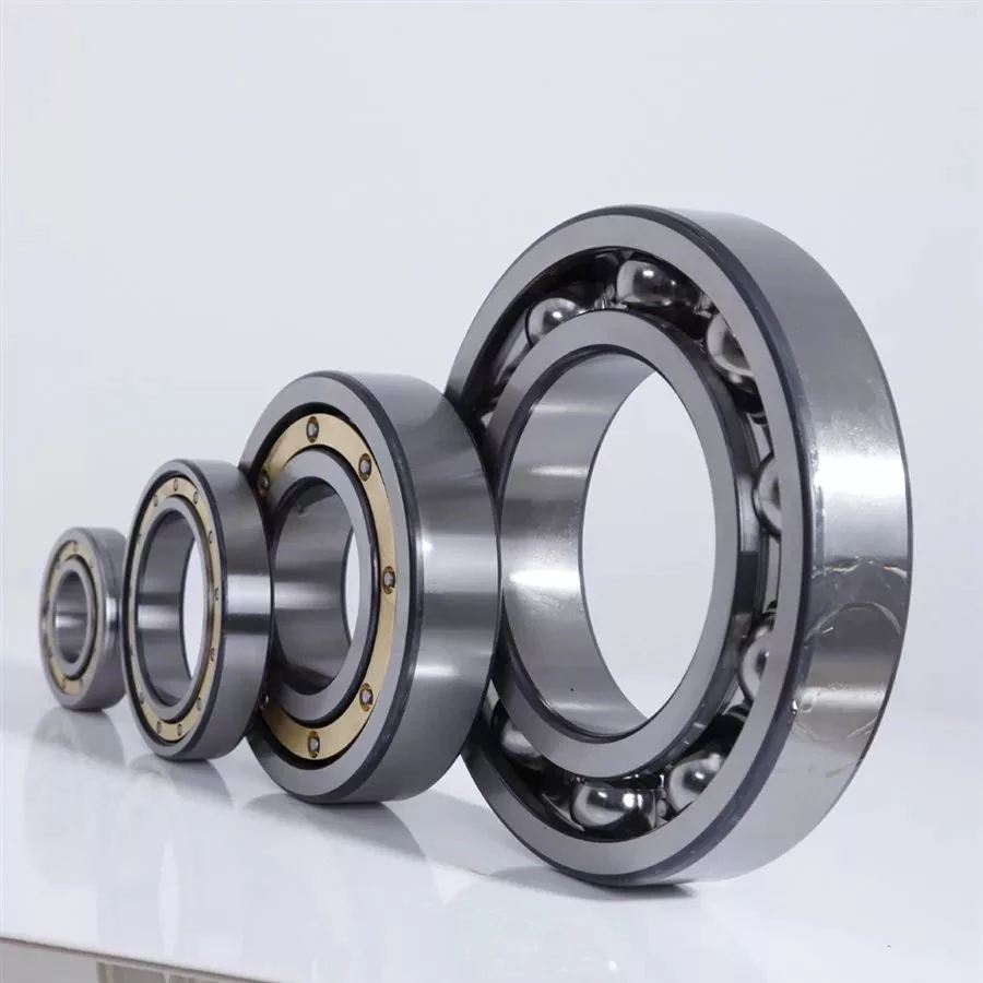
bearing
Ball bearings are made with angular contacts that result in an angle between the bearing’s races. While the axial load moves in one direction through the bearing, the radial load follows a curved path, tending to separate the races axially. In order to minimize this frictional effect, angular contact bearings are designed with the same contact angle on the inner and outer races. The contact angle must be chosen to match the relative proportions of the axial and radial loads. Generally, a larger contact angle supports a higher axial load, while reducing radial load.
Ball bearings are the most common type of angular contact bearings. Angular contact ball bearings are used in many applications, but their primary purpose is in the spindle of a machine tool. These bearings are suitable for high-speed, precision rotation. Their radial load capacity is proportional to the angular contact angle, so larger contact angles tend to enlarge with speed. Angular contact ball bearings are available in single and double-row configurations.
Angular contact ball bearings are a great choice for applications that involve axial loads and complex shapes. These bearings have raceways on the inner and outer rings and mutual displacement along the axial axis. Their axial load bearing capacity increases as the contact Angle a rises. Angular contact ball bearings can withstand loads up to five times their initial weight! For those who are new to bearings, there are many resources online dedicated to the subject.
Despite their complexity, angular contact ball bearings are highly versatile and can be used in a wide range of applications. Their angular contact enables them to withstand moderate radial and thrust loads. Unlike some other bearings, angular contact ball bearings can be positioned in tandem to reduce friction. They also feature a preload mechanism that removes excess play while the bearing is in use.
Angular contact ball bearings are made with different lubricants and cage materials. Standard cages for angular contact ball bearings correspond to Table 1. Some are machined synthetic resins while others are molded polyamide. These cage materials are used to further enhance the bearing’s axial load capacity. Further, angular contact ball bearings can withstand high speeds and radial loads. Compared to radial contact ball bearings, angular contact ball bearings offer the greatest flexibility.

Ball bearings
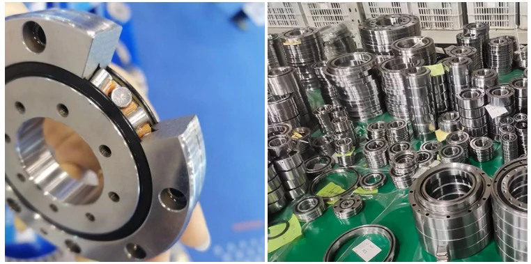
bearing
Ball bearings are circular structures with two separate rings. The smaller ring is mounted on a shaft. The inner ring has a groove on the outer diameter that acts as a path for the balls. Both the inner and outer ring surfaces are finished with very high precision and tolerance. The outer ring is the circular structure with the rolling elements. These elements can take many forms. The inner and outer races are generally made of steel or ceramic.
Silicon nitride ceramic balls have good corrosion resistance and lightweight, but are more expensive than aluminum oxide balls. They also exhibit an insulating effect and are self-lubricating. Silicon nitride is also suitable for high-temperature environments. However, this type of material has the disadvantage of wearing out rapidly and is prone to cracking and shattering, as is the case with bearing steel and glass. It’s also less resistant to heat than aluminum oxide, so it’s best to buy aluminum nitride or ceramic ball bearings for applications that are subjected to extremely high temperatures.
Another type of ball bearings is the thrust bearing. It has a special design that accommodates forces in both axial and radial directions. It is also called a bidirectional bearing because its races are side-by-side. Axial ball bearings use a side-by-side design, and axial balls are used when the loads are transmitted through the wheel. However, they have poor axial support and are prone to separating during heavy radial loads.
The basic idea behind ball bearings is to reduce friction. By reducing friction, you’ll be able to transfer more energy, have less erosion, and improve the life of your machine. With today’s advances in technology, ball bearings can perform better than ever before. From iron to steel to plastics, the materials used in bearings have improved dramatically. Bearings may also incorporate an electromagnetic field. So, it’s best to select the right one for your machine.
The life expectancy of ball bearings depends on many factors, including the operating speed, lubrication, and temperature. A single million-rpm ball bearing can handle between one and five million rotations. As long as its surface contact area is as small as possible, it’s likely to be serviceable for at least one million rotations. However, the average lifespan of ball bearings depends on the application and operating conditions. Fortunately, most bearings can handle a million or more rotations before they start showing signs of fatigue.

Sliding-contact bearings
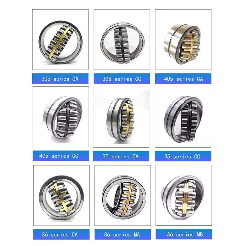
bearing
The basic principle behind sliding-contact bearings is that two surfaces move in contact with one another. This type of bearing works best in situations where the surfaces are made of dissimilar materials. For instance, a steel shaft shouldn’t run in a bronze-lined bore, or vice versa. Instead, one element should be harder than the other, since wear would concentrate in that area. In addition, abrasive particles tend to force themselves into the softer surface, causing a groove to wear in that part.
Sliding-contact bearings have low coefficients of friction and are commonly used in low-speed applications. Unlike ball and roller bearings, sliding contact bearings have to be lubricated on both sides of the contacting surfaces to minimize wear and tear. Sliding-contact bearings generally are made of ceramics, brass, and polymers. Because of their lower friction, they are less accurate than rolling-element bearings.
Sliding-contact bearings are also known as plain or sleeve bearings. They have a sliding motion between their two surfaces, which is reduced by lubrication. This type of bearing is often used in rotary applications and as guide mechanisms. In addition to providing sliding action, sliding-contact bearings are self-lubricating and have high load-carrying capacities. They are typically available in two different types: plain bearings and thrust bearings.
Sliding-contact linear bearing systems consist of a moving structure (called the carriage or slide) and the surfaces on which the two elements slide. The surfaces on which the bearing and journal move are called rails, ways, or guides. A bore hole is a complex geometry, and a minimum oil film thickness h0 is usually used at the line of centers. It is possible to have a sliding-contact bearing in a pillow block.
Because these bearings are porous, they can absorb 15 to 30% of the lubrication oil. This material is commonly used in automobile and machine tools. Many non-metallic materials are used as bearings. One example is rubber, which offers excellent shock absorbency and embeddability. While rubber has poor strength and thermal conductivity, it is commonly used in deep-well pumps and centrifugal pumps. This material has high impact strength, but is not as rigid as steel.

China 2 disc plow for walking tractor board agricultural disc plough baldan disc plough tractor     agricultural equipment partsChina 2 disc plow for walking tractor board agricultural disc plough baldan disc plough tractor     agricultural equipment parts
editor by czh

China best Shenzhen High Precision Metal CNC Machining Custom Manufacturing Agricultural Equipment Machine Machinery Tractor Parts with Good quality

Product Description

HangZhou High precision Metal CNC machining Custom manufacturing agricultural equipment Machine machinery Tractor parts


Click here and specify your inquiry, contact us to get an online quote now!
 

How to get a quote?


1. First: Email us and offer your 3D drawing/2D drawing to us to quote.
2. Second: Let us know the required material, surface finish and special tolerance requirements, quantity information, we’ll arrange for our engineer to review your drawings and quote soon!


Note: Workable 3D Drawing Formats: STEP/IGS/X_T/STL/SOLIDWORKS etc, 2D Drawing with PDF will do.

Project Support: Free Sample Offered Before Production starts
 

Examples projects

What we can offer


Advantages »Free sample offered before production
»Good machining quality and warm service
»Reasonable Pricing and outstanding quality provided
»Competitive shipping cost service with discount sometimes
»MOQ 1PCS and small quantity order accepted, mass production supported
»Professional engineering service when any modification required
»Any turnkey assembly or customized package requirements, we’ll meet your demands!
Equipment

»20 sets of CNC turning machines;

»30 sets of the most technologically advanced machining CNC milling machines;

»25 sets of Multi-Spindle Japan Precision Swiss CNC lathes

RFQ Customer Inquiry →Engineering Communication →Cost Analysis →Sales Analysis →Quote to Customer
» 1-3 Work Days Only
» Submit RFQ with complete commercial terms
Sample Making Sample Order → Engineering Review → Sample Plan to Customer → Sample Status Tracking → Submit Samples with Doc.
» Sample L/T: 1 week
» Continuous Sample Status Tracking
» Complete Documents for sample approval
Order Management CRM System → Open Order Confirm → Logistic Arrangement.
» Production L/T: 2-4 wks
» Weekly Open Order Confirm
» Preferred 3PL Service to Customers
Quality Control Certificates: RoHS, ISO9001:2008, SGS.
IQC → IPQC → OQC/FQC → Quality Complain Feedback → Audit & Training.
» Plant Audit and Qualified by world famous company
» Strict Quality Management Procedure with Traceability
Application »Aerospace
»Automotive
»Lighting fittings
»Motorbike
»PhotoGear
»EDC Tools
» Marine
»Office equipment
»Home appliance
»Medical equipment
»Telecommunication
»Electrical & Electronics
»Fire detection system, etc.

Production information

1). Material Capabilities: Following GB, DIN, and ISO and applying good quality homemade and import materials, we have already provided single/assembly products for international customers mainly from the USA and Europe, etc.

Stainless Steel SS201, SS301, SS303, SS304, SS316, SS416 etc.
Steel Mild steel, Carbon steel, 4140, 4340, Q235, Q345B, 20#, 45#, etc.
Brass HPb63, HPb62, HPb61, HPb59, H59, H62, H68, H80 etc.
Copper C11000, C12000, C12000 C36000 etc.
Aluminum AL6061, Al6063, AL6082, AL7075, AL5052, A380 etc.
Iron A36, 45#, 1213, 12L14, 1215 etc.
Plastic ABS, PC, PE, POM, Delrin, Nylon, PP, PEI, Peek etc.

2). Quality control:
*We have specialized QC testers to check the quality of the products according to different customers’ requirements. Usually, it’s a random inspection, and we also offer 100% inspection at a reasonable price if required.
*We have IQC to check the dimensions and surface of the incoming material
*We have PQC to inspect full-course during the manufacturing processing
*We have FQC to inspect all the anodizing/plating and other finishes’ products from our supplier and proceed with the professional quality and appearance inspection before shipping.


3).Surface Finish: sandblasted/normal and hard anodized finish/polish/coating/polish/passivation/plating/brush/heat treatment/fine glass beads/grounding/tumbled finish , etc. More detailed information for different material parts is below,

Aluminum parts

Brushing
Polishing
Clear Anodized
Color Anodized
Sandblast Anodized
Chemical Film
Stainless Steel parts Polishing
Passivated
Sandblasting
Plating
Steel Parts Zinc plating
Oxide Black
Nickel plating
Chrome plating
Carburized
Heat treatment
Powder Coated
Plastic Parts Chrome plating
Polishing

4). Payment terms: T/T payment. The Sample order is paid by full payment; Mass production with order amount exceeding can be paid a 50% deposit before production, and balance paid before shipping.

5). Production schedule: Usually, it takes 5~10 working days for sample production; 15~20 working days for mass production days, it depends on your design, simple parts can be produced quickly, the complicated design parts would take us more machining time.

6). Machining capability: 30 sets of the most technologically advanced machining CNC milling machines, 20 sets of CNC turning machines, 25 sets of Multi-Spindle Japan Precision Swiss CNC lathes, and 4 sets of 2D &3D CMM (image measuring instrument) quality control equipment 3 QC staff, enabling CNC Manufacturing to deliver precise parts within the tightest of tolerances, ensuring the highest quality results to meet different
customers’ requirements.

7). Tolerance: +/- 0.02mm (for Metal shaft), +/-0.03mm ( for plastic), for special tolerance requirements, please point them out in the email, we will Check if it’s feasible to make it after studying it.

8). Packing & Shipping way:

1. Packing Detail: Each product is packed with plastic preservative, EPE, foam plastic bag, Carton outside, wood case or iron case or as per the customer’s special requirement. Besides, the custom package takes a week to prepare in advance.

2. Delivery Detail: the fast International Shipping time takes 3 ~5 working days by DHL/UPS/FedEx, slow shipping time takes 7~ 8 working days by DHL/UPS/FedEx/TNT, etc.

3. Shipping options:
1) 0-100kg: express&air freight priority,
2) >100kg: sea freight priority,
3) As per customized specifications

About us

Full-service precision CNC machining services for prototypes and short and low to high production runs. Capabilities are CNC milled and turned metal parts and assemblies. Materials worked with include aluminum, brass, copper, stainless, steel, iron, other precious metals, and other plastic materials. Lead times are 2 to 3 weeks for prototypes and 4 to 6 weeks for production runs. Emergency and rush services are available. Industries served include aircraft and aerospace, consumer electronics, automotive, machinery fittings, audio equipment, EDC tools, computer, and Secondary processes such as anodizing, sandblasting, blackening, grinding, honing, heat treating, powder coating, passivation, polishing, plating, and brushing are also provided.

We put high attention and effort into all of the work that we do. Every part that comes off our machines is an extension of us. We take great pride in bringing machining CZPT to our customers. The amazing quality parts we machined here will be your best choice to find a supplier!


Customer’s comment


Want to know more about us? Email us now!


Drive shaft type

The driveshaft transfers torque from the engine to the wheels and is responsible for the smooth running of the vehicle. Its design had to compensate for differences in length and angle. It must also ensure perfect synchronization between its joints. The drive shaft should be made of high-grade materials to achieve the best balance of stiffness and elasticity. There are 3 main types of drive shafts. These include: end yokes, tube yokes and tapered shafts.
air-compressor

tube yoke

Tube yokes are shaft assemblies that use metallic materials as the main structural component. The yoke includes a uniform, substantially uniform wall thickness, a first end and an axially extending second end. The first diameter of the drive shaft is greater than the second diameter, and the yoke further includes a pair of opposing lugs extending from the second end. These lugs have holes at the ends for attaching the axle to the vehicle.
By retrofitting the driveshaft tube end into a tube fork with seat. This valve seat transmits torque to the driveshaft tube. The fillet weld 28 enhances the torque transfer capability of the tube yoke. The yoke is usually made of aluminum alloy or metal material. It is also used to connect the drive shaft to the yoke. Various designs are possible.
The QU40866 tube yoke is used with an external snap ring type universal joint. It has a cup diameter of 1-3/16″ and an overall width of 4½”. U-bolt kits are another option. It has threaded legs and locks to help secure the yoke to the drive shaft. Some performance cars and off-road vehicles use U-bolts. Yokes must be machined to accept U-bolts, and U-bolt kits are often the preferred accessory.
The end yoke is the mechanical part that connects the drive shaft to the stub shaft. These yokes are usually designed for specific drivetrain components and can be customized to your needs. Pat’s drivetrain offers OEM replacement and custom flanged yokes.
If your tractor uses PTO components, the cross and bearing kit is the perfect tool to make the connection. Additionally, cross and bearing kits help you match the correct yoke to the shaft. When choosing a yoke, be sure to measure the outside diameter of the U-joint cap and the inside diameter of the yoke ears. After taking the measurements, consult the cross and bearing identification drawings to make sure they match.
While tube yokes are usually easy to replace, the best results come from a qualified machine shop. Dedicated driveshaft specialists can assemble and balance finished driveshafts. If you are unsure of a particular aspect, please refer to the TM3000 Driveshaft and Cardan Joint Service Manual for more information. You can also consult an excerpt from the TSB3510 manual for information on angle, vibration and runout.
The sliding fork is another important part of the drive shaft. It can bend over rough terrain, allowing the U-joint to keep spinning in tougher conditions. If the slip yoke fails, you will not be able to drive and will clang. You need to replace it as soon as possible to avoid any dangerous driving conditions. So if you notice any dings, be sure to check the yoke.
If you detect any vibrations, the drivetrain may need adjustment. It’s a simple process. First, rotate the driveshaft until you find the correct alignment between the tube yoke and the sliding yoke of the rear differential. If there is no noticeable vibration, you can wait for a while to resolve the problem. Keep in mind that it may be convenient to postpone repairs temporarily, but it may cause bigger problems later.
air-compressor

end yoke

If your driveshaft requires a new end yoke, CZPT has several drivetrain options. Our automotive end yoke inventory includes keyed and non-keyed options. If you need tapered or straight holes, we can also make them for you.
A U-bolt is an industrial fastener that has U-shaped threads on its legs. They are often used to join 2 heads back to back. These are convenient options to help keep drivetrain components in place when driving over rough terrain, and are generally compatible with a variety of models. U-bolts require a specially machined yoke to accept them, so be sure to order the correct size.
The sliding fork helps transfer power from the transfer case to the driveshaft. They slide in and out of the transfer case, allowing the u-joint to rotate. Sliding yokes or “slips” can be purchased separately. Whether you need a new 1 or just a few components to upgrade your driveshaft, 4 CZPT Parts will have the parts you need to repair your vehicle.
The end yoke is a necessary part of the drive shaft. It connects the drive train and the mating flange. They are also used in auxiliary power equipment. CZPT’s drivetrains are stocked with a variety of flanged yokes for OEM applications and custom builds. You can also find flanged yokes for constant velocity joints in our extensive inventory. If you don’t want to modify your existing drivetrain, we can even make a custom yoke for you.

China best Shenzhen High Precision Metal CNC Machining Custom Manufacturing Agricultural Equipment Machine Machinery Tractor Parts     with Good qualityChina best Shenzhen High Precision Metal CNC Machining Custom Manufacturing Agricultural Equipment Machine Machinery Tractor Parts     with Good quality

China factory Agricultural Machine Equipment Farm Tractor 45HP 4X4wd Mini Diesel Power Engine Technical Parts with Hot selling

Product Description

Agricultural Machine Equipment Farm Tractor 45hp 4x4wd Mini Diesel Power Engine Technical Parts

Product Overview

The shift synchronizer makes shifting lighter and convenient.
Equipped flat tire as standard,Paddy tire optional.
Adopt transmission 8+8 shuttle for easier operation, which caters to different needs.

FEATURES AT A GLANCE

Good sealing perforamnce of axles ensure working in water or deep mud field.
Use double steering cylinders on front axle for reducing turning radius.
Air brake is optional for road transport.
High quality bearings are used for long work prolonging work life.
Equipped ROPS&Canopy as standard,Cabin optional for comfort.


PRODUCT SPECIFICATIONS

Company Profile

WORLD A/M has been dedicated to becoming a worldwide first-class agriculture machinery manufacture in the past decade. By high-quality products and customer-oriented service support, the company’s products command a good market both at home and in 58
countries and regions overseas. So far, more than 350,000 WORLD machines have been sold and uesd globally.


Analytical Approaches to Estimating Contact Pressures in Spline Couplings

A spline coupling is a type of mechanical connection between 2 rotating shafts. It consists of 2 parts – a coupler and a coupling. Both parts have teeth which engage and transfer loads. However, spline couplings are typically over-dimensioned, which makes them susceptible to fatigue and static behavior. Wear phenomena can also cause the coupling to fail. For this reason, proper spline coupling design is essential for achieving optimum performance.
splineshaft

Modeling a spline coupling

Spline couplings are becoming increasingly popular in the aerospace industry, but they operate in a slightly misaligned state, causing both vibrations and damage to the contact surfaces. To solve this problem, this article offers analytical approaches for estimating the contact pressures in a spline coupling. Specifically, this article compares analytical approaches with pure numerical approaches to demonstrate the benefits of an analytical approach.
To model a spline coupling, first you create the knowledge base for the spline coupling. The knowledge base includes a large number of possible specification values, which are related to each other. If you modify 1 specification, it may lead to a warning for violating another. To make the design valid, you must create a spline coupling model that meets the specified specification values.
After you have modeled the geometry, you must enter the contact pressures of the 2 spline couplings. Then, you need to determine the position of the pitch circle of the spline. In Figure 2, the centre of the male coupling is superposed to that of the female spline. Then, you need to make sure that the alignment meshing distance of the 2 splines is the same.
Once you have the data you need to create a spline coupling model, you can begin by entering the specifications for the interface design. Once you have this data, you need to choose whether to optimize the internal spline or the external spline. You’ll also need to specify the tooth friction coefficient, which is used to determine the stresses in the spline coupling model 20. You should also enter the pilot clearance, which is the clearance between the tip 186 of a tooth 32 on 1 spline and the feature on the mating spline.
After you have entered the desired specifications for the external spline, you can enter the parameters for the internal spline. For example, you can enter the outer diameter limit 154 of the major snap 54 and the minor snap 56 of the internal spline. The values of these parameters are displayed in color-coded boxes on the Spline Inputs and Configuration GUI screen 80. Once the parameters are entered, you’ll be presented with a geometric representation of the spline coupling model 20.

Creating a spline coupling model 20

The spline coupling model 20 is created by a product model software program 10. The software validates the spline coupling model against a knowledge base of configuration-dependent specification constraints and relationships. This report is then input to the ANSYS stress analyzer program. It lists the spline coupling model 20’s geometric configurations and specification values for each feature. The spline coupling model 20 is automatically recreated every time the configuration or performance specifications of the spline coupling model 20 are modified.
The spline coupling model 20 can be configured using the product model software program 10. A user specifies the axial length of the spline stack, which may be zero, or a fixed length. The user also enters a radial mating face 148, if any, and selects a pilot clearance specification value of 14.5 degrees or 30 degrees.
A user can then use the mouse 110 to modify the spline coupling model 20. The spline coupling knowledge base contains a large number of possible specification values and the spline coupling design rule. If the user tries to change a spline coupling model, the model will show a warning about a violation of another specification. In some cases, the modification may invalidate the design.
In the spline coupling model 20, the user enters additional performance requirement specifications. The user chooses the locations where maximum torque is transferred for the internal and external splines 38 and 40. The maximum torque transfer location is determined by the attachment configuration of the hardware to the shafts. Once this is selected, the user can click “Next” to save the model. A preview of the spline coupling model 20 is displayed.
The model 20 is a representation of a spline coupling. The spline specifications are entered in the order and arrangement as specified on the spline coupling model 20 GUI screen. Once the spline coupling specifications are entered, the product model software program 10 will incorporate them into the spline coupling model 20. This is the last step in spline coupling model creation.
splineshaft

Analysing a spline coupling model 20

An analysis of a spline coupling model consists of inputting its configuration and performance specifications. These specifications may be generated from another computer program. The product model software program 10 then uses its internal knowledge base of configuration dependent specification relationships and constraints to create a valid three-dimensional parametric model 20. This model contains information describing the number and types of spline teeth 32, snaps 34, and shoulder 36.
When you are analysing a spline coupling, the software program 10 will include default values for various specifications. The spline coupling model 20 comprises an internal spline 38 and an external spline 40. Each of the splines includes its own set of parameters, such as its depth, width, length, and radii. The external spline 40 will also contain its own set of parameters, such as its orientation.
Upon selecting these parameters, the software program will perform various analyses on the spline coupling model 20. The software program 10 calculates the nominal and maximal tooth bearing stresses and fatigue life of a spline coupling. It will also determine the difference in torsional windup between an internal and an external spline. The output file from the analysis will be a report file containing model configuration and specification data. The output file may also be used by other computer programs for further analysis.
Once these parameters are set, the user enters the design criteria for the spline coupling model 20. In this step, the user specifies the locations of maximum torque transfer for both the external and internal spline 38. The maximum torque transfer location depends on the configuration of the hardware attached to the shafts. The user may enter up to 4 different performance requirement specifications for each spline.
The results of the analysis show that there are 2 phases of spline coupling. The first phase shows a large increase in stress and vibration. The second phase shows a decline in both stress and vibration levels. The third stage shows a constant meshing force between 300N and 320N. This behavior continues for a longer period of time, until the final stage engages with the surface.
splineshaft

Misalignment of a spline coupling

A study aimed to investigate the position of the resultant contact force in a spline coupling engaging teeth under a steady torque and rotating misalignment. The study used numerical methods based on Finite Element Method (FEM) models. It produced numerical results for nominal conditions and parallel offset misalignment. The study considered 2 levels of misalignment – 0.02 mm and 0.08 mm – with different loading levels.
The results showed that the misalignment between the splines and rotors causes a change in the meshing force of the spline-rotor coupling system. Its dynamics is governed by the meshing force of splines. The meshing force of a misaligned spline coupling is related to the rotor-spline coupling system parameters, the transmitting torque, and the dynamic vibration displacement.
Despite the lack of precise measurements, the misalignment of splines is a common problem. This problem is compounded by the fact that splines usually feature backlash. This backlash is the result of the misaligned spline. The authors analyzed several splines, varying pitch diameters, and length/diameter ratios.
A spline coupling is a two-dimensional mechanical system, which has positive backlash. The spline coupling is comprised of a hub and shaft, and has tip-to-root clearances that are larger than the backlash. A form-clearance is sufficient to prevent tip-to-root fillet contact. The torque on the splines is transmitted via friction.
When a spline coupling is misaligned, a torque-biased thrust force is generated. In such a situation, the force can exceed the torque, causing the component to lose its alignment. The two-way transmission of torque and thrust is modeled analytically in the present study. The analytical approach provides solutions that can be integrated into the design process. So, the next time you are faced with a misaligned spline coupling problem, make sure to use an analytical approach!
In this study, the spline coupling is analyzed under nominal conditions without a parallel offset misalignment. The stiffness values obtained are the percentage difference between the nominal pitch diameter and load application diameter. Moreover, the maximum percentage difference in the measured pitch diameter is 1.60% under a torque of 5000 N*m. The other parameter, the pitch angle, is taken into consideration in the calculation.

China factory Agricultural Machine Equipment Farm Tractor 45HP 4X4wd Mini Diesel Power Engine Technical Parts     with Hot sellingChina factory Agricultural Machine Equipment Farm Tractor 45HP 4X4wd Mini Diesel Power Engine Technical Parts     with Hot selling

China Standard Good Service China Agricultural Equipment Factory Manufacturer to Supply Lifelong Tractor Parts for 25-280HP Farm CZPT with high quality

Product Description

Good service China agricultural equipment factory manufacturer to supply lifelong tractor parts for 25-280HP Farm Tractors

Tractor Main Features and Advantages:

1.Equipped famous brand engine showing advanced capacity,low fuel consumption,high economic efficiency.
2. Streamlined appearance design, beautiful and generous.
3.Transmission Case adopt meshed shift and add the gearbox interlock device makes the operation more smoothly,reliable and easier.
4. Double action clutch with disc spring, perform steadily and easy to operate.
5. Fully hydraulic steering system greatly reduced driver’s work strength.
6. Wet disc brake device, reliable brake performance.
7. Separate injection of hydraulic oil, reliable to operate.
8. The lifter with force and position adjustment, with reliable lift.
9. Tractor PTO:
PTO in Double speed : 540/760r/min Optional, For high working efficiency.
PTO shaft of 6 or 8 spline Optional, adaptable for agricultural equipment of all over the world. 
10. Big Chassis and Heavy-duty Rear axle for Durable Strong machine.
11. Full series light, ROPS,Sunshade/Canopy, Fan/Heater/Air-conditioned cabin are all available, for more comfortable driving environment. 

Tractor detail show :

Advance Production workshop :

Strictly inspect for every set machine before Goods Delivery :
Various Packing and Transporting ways to meet customers special request :

Perfect after-sale service for both Distributors and Private customers:

Please contact us if you have any demand for our product :

John li
Sales Director

HangZhou Yourchance Machinery Co., Ltd.
ADD: No.5097 CZPT East Street,HangZhou,China.
TEL:   

Best price will be quoted for you as soon as receive your Requirement !

The Four Basic Components of a Screw Shaft

There are 4 basic components of a screw shaft: the Head, the Thread angle, and the Threaded shank. These components determine the length, shape, and quality of a screw. Understanding how these components work together can make purchasing screws easier. This article will cover these important factors and more. Once you know these, you can select the right type of screw for your project. If you need help choosing the correct type of screw, contact a qualified screw dealer.

Thread angle

The angle of a thread on a screw shaft is the difference between the 2 sides of the thread. Threads that are unified have a 60 degree angle. Screws have 2 parts: a major diameter, also known as the screw’s outside diameter, and a minor diameter, or the screw’s root diameter. A screw or nut has a major diameter and a minor diameter. Each has its own angle, but they all have 1 thing in common – the angle of thread is measured perpendicularly to the screw’s axis.
The pitch of a screw depends on the helix angle of the thread. In a single-start screw, the lead is equal to the pitch, and the thread angle of a multiple-start screw is based on the number of starts. Alternatively, you can use a square-threaded screw. Its square thread minimizes the contact surface between the nut and the screw, which improves efficiency and performance. A square thread requires fewer motors to transfer the same load, making it a good choice for heavy-duty applications.
A screw thread has 4 components. First, there is the pitch. This is the distance between the top and bottom surface of a nut. This is the distance the thread travels in a full revolution of the screw. Next, there is the pitch surface, which is the imaginary cylinder formed by the average of the crest and root height of each tooth. Next, there is the pitch angle, which is the angle between the pitch surface and the gear axis.
screwshaft

Head

There are 3 types of head for screws: flat, round, and hexagonal. They are used in industrial applications and have a flat outer face and a conical interior. Some varieties have a tamper-resistant pin in the head. These are usually used in the fabrication of bicycle parts. Some are lightweight, and can be easily carried from 1 place to another. This article will explain what each type of head is used for, and how to choose the right 1 for your screw.
The major diameter is the largest diameter of the thread. This is the distance between the crest and the root of the thread. The minor diameter is the smaller diameter and is the distance between the major and minor diameters. The minor diameter is half the major diameter. The major diameter is the upper surface of the thread. The minor diameter corresponds to the lower extreme of the thread. The thread angle is proportional to the distance between the major and minor diameters.
Lead screws are a more affordable option. They are easier to manufacture and less expensive than ball screws. They are also more efficient in vertical applications and low-speed operations. Some types of lead screws are also self-locking, and have a high coefficient of friction. Lead screws also have fewer parts. These types of screw shafts are available in various sizes and shapes. If you’re wondering which type of head of screw shaft to buy, this article is for you.

Threaded shank

Wood screws are made up of 2 parts: the head and the shank. The shank is not threaded all the way up. It is only partially threaded and contains the drive. This makes them less likely to overheat. Heads on wood screws include Oval, Round, Hex, Modified Truss, and Flat. Some of these are considered the “top” of the screw.
Screws come in many sizes and thread pitches. An M8 screw has a 1.25-mm thread pitch. The pitch indicates the distance between 2 identical threads. A pitch of 1 is greater than the other. The other is smaller and coarse. In most cases, the pitch of a screw is indicated by the letter M followed by the diameter in millimetres. Unless otherwise stated, the pitch of a screw is greater than its diameter.
Generally, the shank diameter is smaller than the head diameter. A nut with a drilled shank is commonly used. Moreover, a cotter pin nut is similar to a castle nut. Internal threads are usually created using a special tap for very hard metals. This tap must be followed by a regular tap. Slotted machine screws are usually sold packaged with nuts. Lastly, studs are often used in automotive and machine applications.
In general, screws with a metric thread are more difficult to install and remove. Fortunately, there are many different types of screw threads, which make replacing screws a breeze. In addition to these different sizes, many of these screws have safety wire holes to keep them from falling. These are just some of the differences between threaded screw and non-threaded. There are many different types of screw threads, and choosing the right 1 will depend on your needs and your budget.
screwshaft

Point

There are 3 types of screw heads with points: cone, oval, and half-dog. Each point is designed for a particular application, which determines its shape and tip. For screw applications, cone, oval, and half-dog points are common. Full dog points are not common, and they are available in a limited number of sizes and lengths. According to ASTM standards, point penetration contributes as much as 15% of the total holding power of the screw, but a cone-shaped point may be more preferred in some circumstances.
There are several types of set screws, each with its own advantage. Flat-head screws reduce indentation and frequent adjustment. Dog-point screws help maintain a secure grip by securing the collar to the screw shaft. Cup-point set screws, on the other hand, provide a slip-resistant connection. The diameter of a cup-point screw is usually half of its shaft diameter. If the screw is too small, it may slack and cause the screw collar to slip.
The UNF series has a larger area for tensile stress than coarse threads and is less prone to stripping. It’s used for external threads, limited engagement, and thinner walls. When using a UNF, always use a standard tap before a specialized tap. For example, a screw with a UNF point is the same size as a type C screw but with a shorter length.

Spacer

A spacer is an insulating material that sits between 2 parts and centers the shaft of a screw or other fastener. Spacers come in different sizes and shapes. Some of them are made of Teflon, which is thin and has a low coefficient of friction. Other materials used for spacers include steel, which is durable and works well in many applications. Plastic spacers are available in various thicknesses, ranging from 4.6 to 8 mm. They’re suitable for mounting gears and other items that require less contact surface.
These devices are used for precision fastening applications and are essential fastener accessories. They create clearance gaps between the 2 joined surfaces or components and enable the screw or bolt to be torqued correctly. Here’s a quick guide to help you choose the right spacer for the job. There are many different spacers available, and you should never be without one. All you need is a little research and common sense. And once you’re satisfied with your purchase, you can make a more informed decision.
A spacer is a component that allows the components to be spaced appropriately along a screw shaft. This tool is used to keep space between 2 objects, such as the spinning wheel and an adjacent metal structure. It also helps ensure that a competition game piece doesn’t rub against an adjacent metal structure. In addition to its common use, spacers can be used in many different situations. The next time you need a spacer, remember to check that the hole in your screw is threaded.
screwshaft

Nut

A nut is a simple device used to secure a screw shaft. The nut is fixed on each end of the screw shaft and rotates along its length. The nut is rotated by a motor, usually a stepper motor, which uses beam coupling to accommodate misalignments in the high-speed movement of the screw. Nuts are used to secure screw shafts to machined parts, and also to mount bearings on adapter sleeves and withdrawal sleeves.
There are several types of nut for screw shafts. Some have radial anti-backlash properties, which prevent unwanted radial clearances. In addition, they are designed to compensate for thread wear. Several nut styles are available, including anti-backlash radial nuts, which have a spring that pushes down on the nut’s flexible fingers. Axial anti-backlash nuts also provide thread-locking properties.
To install a ball nut, you must first align the tangs of the ball and nut. Then, you must place the adjusting nut on the shaft and tighten it against the spacer and spring washer. Then, you need to lubricate the threads, the ball grooves, and the spring washers. Once you’ve installed the nut, you can now install the ball screw assembly.
A nut for screw shaft can be made with either a ball or a socket. These types differ from hex nuts in that they don’t need end support bearings, and are rigidly mounted at the ends. These screws can also have internal cooling mechanisms to improve rigidity. In this way, they are easier to tension than rotating screws. You can also buy hollow stationary screws for rotator nut assemblies. This type is great for applications requiring high heat and wide temperature changes, but you should be sure to follow the manufacturer’s instructions.

China Standard Good Service China Agricultural Equipment Factory Manufacturer to Supply Lifelong Tractor Parts for 25-280HP Farm CZPT     with high qualityChina Standard Good Service China Agricultural Equipment Factory Manufacturer to Supply Lifelong Tractor Parts for 25-280HP Farm CZPT     with high quality